
Digital Galton Board Simulation
This page details a digital galton board running on an RP2040 for I made with Andrew Shim. This was for ECE 5730 at Cornell University.

Introduction:
The goal of this lab was to design and implement a digital Galton board using the RP2040 microcontroller, simulating a physical probability experiment in which balls fall through an array of pegs, ultimately forming a histogram that approximates a Gaussian distribution. The project required generating an interactive display on a VGA screen while ensuring real-time performance constraints were met.
Additionally, the implementation incorporated audio feedback and user-controlled parameters via a potentiometer and button inputs. The lab served as an exercise in digital systems design, emphasizing concepts such as fixed-point arithmetic, real-time processing, and efficient memory management. By optimizing both hardware and software components, we aimed to maximize the number of active balls while maintaining a stable frame rate above 30 FPS. Throughout the project, we explored key principles of randomness, probability distributions, and the central limit theorem, all within the constraints of the RP2040’s processing power and memory resources.
Design and Testing Methods:
Hardware Design
Our Development process moved in stages, accomplishing specific checkpoints over 3 weeks. The hardware design of our digital Galton board was centered around the RP2040 microcontroller, utilizing its GPIO capabilities to interface with VGA output, audio generation, and user input controls. The VGA output required precise timing to generate a stable display, making use of dedicated PIO blocks to handle synchronization signals. The VGA pin assignments included horizontal and vertical sync signals, as well as RGB data lines. We also included a secondary green data line with an alternate resistor to achieve a greater range of color variety. Audio output was implemented via SPI using DMA, ensuring that sound effects played efficiently without interrupting the main execution loop.
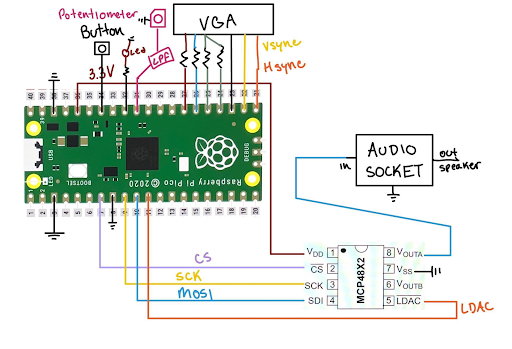
Figure 1: Wiring Layout Diagram
To enable user interaction, a potentiometer and a button were integrated into the system. The potentiometer allowed dynamic adjustment of simulation parameters, such as the number of active balls, gravity, and bounciness, while the button toggled between these settings. Implementing a debounce mechanism for the button ensured reliable input recognition, preventing unintended state changes. Additionally, an LED indicator was included to signal frame drops, providing a simple yet effective diagnostic tool for monitoring system performance.
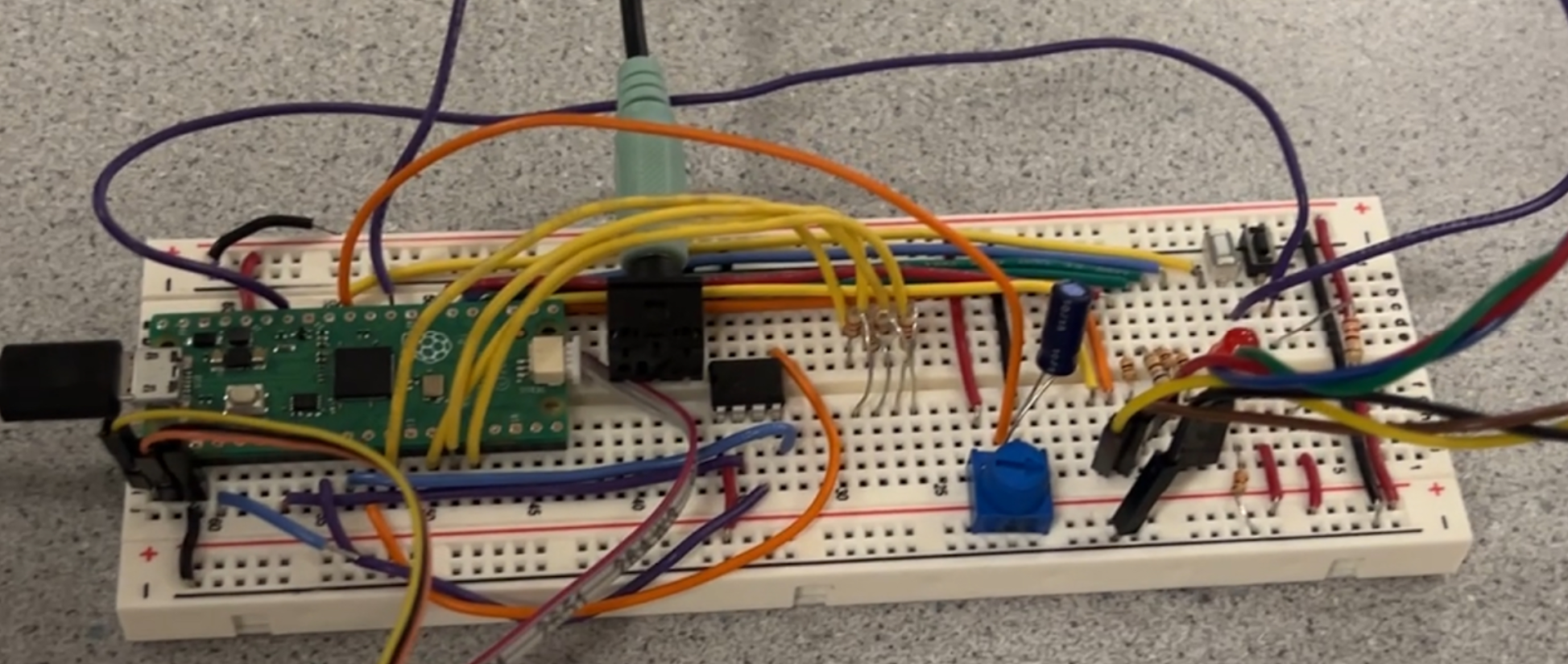
Figure 2: Final Breadboard Setup
One of the key hardware challenges encountered was noise interference from long wire connections, particularly affecting the potentiometer readings. The high-frequency signals from the VGA data lines introduced significant noise, which was mitigated using a combination of physical and digital low-pass filters. This experience highlighted the importance of careful circuit design, especially in mixed-signal environments where analog components are susceptible to digital noise. Future designs would benefit from shorter analog signal paths and better isolation from high-speed digital signals.
Software Design
The software for Lab 1 was to generate a Digital Galton Board on a VGA screen, and it was built on two example programs: animation.c and dma-demo.c. These example programs provided the framework for interacting with generating graphs on VGA and generating sound through DMA. The code was modified to include functions such as generating a 16-row Galton Board, making sound when a ball hits a peg, adding a histogram to display ball distribution, a data display, and a potentiometer to control the parameters of the Galton Board, which is augmented with a push button to cycle through the three adjustable parameters. At the end of the lab, the program can allow over 5,000 balls active at the same time while still having a frame rate that higher than 30 per second.
Every ball is spawned in at the top center of the VGA display, at the position of (320, 66). The random distribution of balls through the galton board is created through a use of a random initial x-velocity in the range of (-1, 1]. A fix15 value of this range can be efficiently calculated through the rand() function, masking the 32-bit output to the lower 16 bits for a range of [0, 2), and subtracting the result from 1.
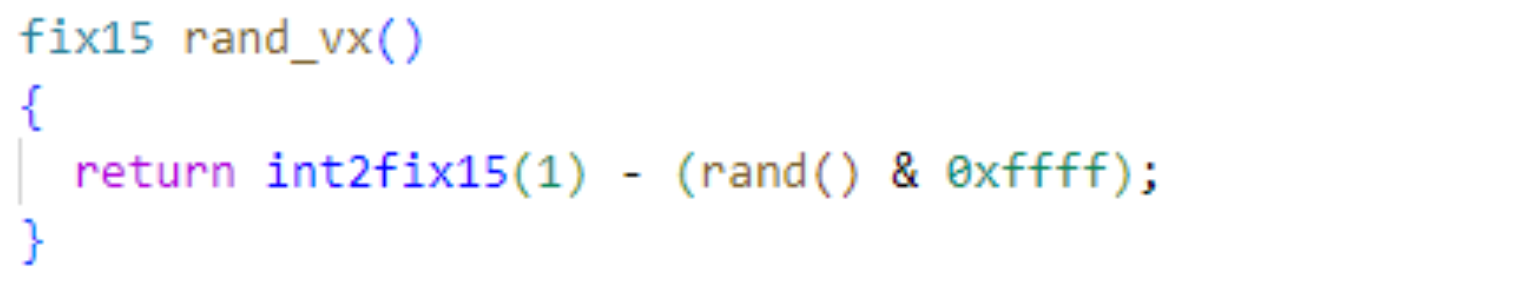
Figure 3: Helper Function for Random Generation of Initial x-velocity
Each ball’s position is updated on every frame, taking into account gravitation acceleration and any collisions with pegs. Collisions between balls were not modelled in this simulation. Gravitational acceleration was modeled by increasing the y-velocity by a set value on every iteration. We chose an initial gravity value of 0.75, and this is one parameter adjustable through the potentiometer.
Collision physics were calculated based on the x and y values of each ball compared to the pegs. The distance between a ball and a peg is calculated with the alpha max plus beta min algorithm, a fast approximation for the square root of the sum of squares. If the calculated distance is less than the sum of radii for the peg and ball (6 + 1= 7), then a collision is detected. We follow through, calculating the normal angle between the peg and ball. An acceleration in the normal direction is simulated by adding some velocity in that direction.
When a collision occurs, a short “thunk” sound is generated through the speakers. This audio signal is handled through a DMA channel in order to save cpu cycles on audio synthesis. We first check that the DMA channel isn’t already generating a sound. If not, then we set the data channel’s read address to the beginning of the DAC_data, and set it active with the dma_start_channel_mask function.
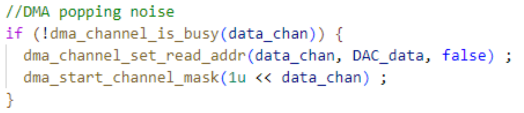
Figure 4: Sound Generation through DMA Channel
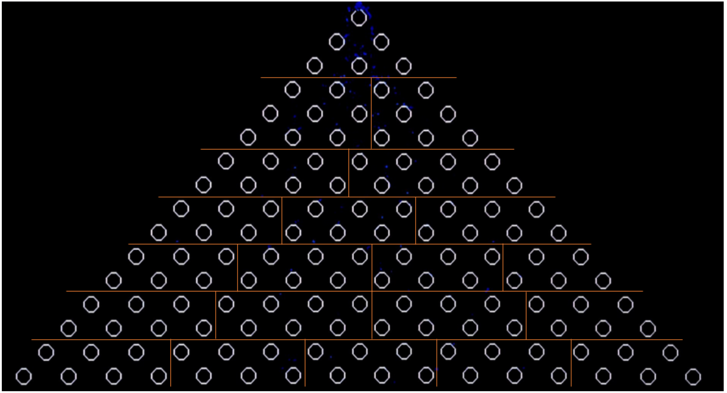
Figure 5: Galton Board Segmentation, 21 Sections of <8 Pegs Each
The collision physics calculation provided an opportunity to massively optimize the compute time of our program. Because this code is repeated for every ball being drawn on frame, slight improvements led to massive compounding gains. The initial version of our code iterated through every ball, then compared each ball to every peg. Through testing, we implemented a function that checks the ball’s x and y positions to localize the ball to a section of the galton board with a set number of pegs. This is implemented in return_peg_div_indx(). Through testing, we chose to segment the galton board into 21 divisions with up to 8 pegs each. This means that the aforementioned collision physics loop runs less than 8 times per ball per frame. The effects of various galton board segmentations are evaluated in the results section of this lab report. For the data displayer for active ball numbers, the total ball used, times, bounciness, and gravity, the following logic was used:
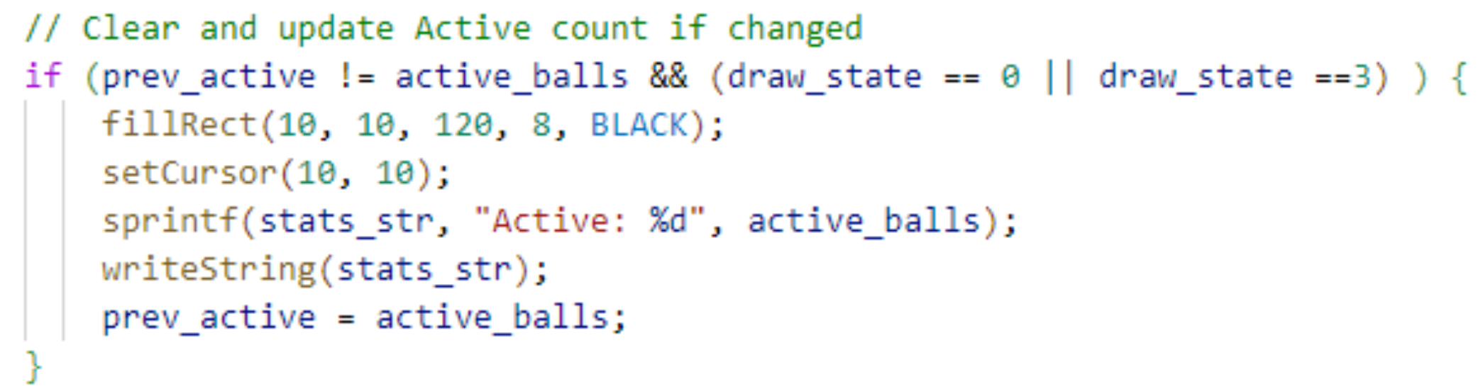
Figure 6: Logic for Data Displayer (same logic for number of balls, active time, etc.)
All prev_data was initialized as -1, so when new data is collected, the displayer will be updated. Whenever the program is activated, it will erase previous text on the VGA screen and write the latest data to the VGA screen. After the latest data is displayed, the program will store the latest data as previous data and wait for the next comparison and activation. The code shown above is only a template, in the code shown in the appendix, the “data” was replaced by the real data going to be displayed like active ball number, total ball number, and etc.
For the button to switch the state potentiometer control, has a similar debounce logic to Lab 1. It will debounce the input and change the state when it becomes pressed. When the state of the button changes, the potentiometer’s change will cause the change of another parameter. When it changes to state 0, which is the initial state and reset state, the active ball number, bounciness, gravity, histogram, and total ball number will be reset in this state. For state 1/2/3, the potentiometer will change the active ball number, bounciness, and gravity using the code below:

Figure 7: Logic to Change Active Ball Number, Bounciness, and Gravity
Following the code shown above, since the reading of the potentiometer meter (raw) has a range from 0 to 4095, there were 4096 discrete levels. The new data will be calculated by the code shown above based on the reading of the potentiometer. Moreover, when the state of the potentiometer is set to reset mode, the new data will be set to the initial data. Moreover, in state 1/2/3, the change of the potentiometer will also cause a reset of the histogram and the total number of balls by clearing the entire histogram while resetting all of its heights to 0 and reset the total number of balls in the data display section.
For the histogram part, the height of each section is based on the normalized ball numbers that fell into that section. It was normalized by the formula:
Height = Maximum Height(balls in this slot - balls in lowest slot) / (balls in height slot - balls in lowest slot)
After the height is calculated, shown as in the code below, when the new height is lower than the original height, the change in the height will be removed from the bar top by drawing a black rectangle. However, if the new height is higher, a new rectangle will be drawn in order to display the new histogram. Considering the resolution of the VGA display, the slot width of each bar was set as 34. When the histogram needs to be reset, the height, old_height, and number of balls in each section will be reset to 0 and the histogram can be completely reset.
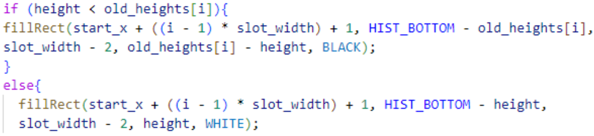
Figure 8: Histogram Logic
Results:
Our digital galton board simulation on the RP2040 was able to achieve the simulation of 5050 balls while meeting the 30 fps deadline. This was made possible through a combination of software optimizations and a system clock speed overclock to 250 MHz. The simulation runs on a single core of the RP2040, and using multicore will enable future improvements.
The testing of the digital galton board simulation relied partly on qualitative observations, and partly on quantitative measurements. The qualitative evaluation of a display output can be summarized by the following simple question: “Does this [item/function/behaviour] look correct?”. The testing methodology simply requires uploading the new code onto the pico simulation and carefully observing the behavior on the VGA display output. We took special care to remove any bright flashing that may be considered on-screen artifacts from drawing and clearing objects. We removed flashing from our histogram by including additional logic to partly update histogram heights rather than drawing the entire bar. Similarly, balls would flash in and out of existence from minor disturbances of the potentiometer. Determining which specific balls should be removed from the screen reduced the ball flashing to an imperceptible level. Updating the on-screen text outputs such as # of active balls, on every frame, led to problems in legibility of the text. We reduced the refresh rate of these values down to 5/10 times per second, massively increasing legibility. These quality improvements above were achieved through either reducing the number of updates per second, or by reducing the number of pixels updated each frame. In either case, this had a secondary positive effect of reducing the system compute time, allowing for more balls to be simulated.
The other qualitative improvement, though somewhat obvious, focuses on the behavior of each ball. For the purposes of this project, highly accurate simulation of collision physics is not necessary. However, we focused on improving the simulation to make it “look correct” to the eye. An example is the use of the alpha max plus beta min algorithm used to quickly approximate the square root of the sum of squares. While use of α = 1, β = 0.25 would have allowed faster computation by the use of two right shifts, we were unhappy with the behavior, which varied too much from the correct square root calculation. We chose a middle ground of α = 1, which requires no computation for the max value, but β = 0.3978247, which requires one fixed point multiplication.
This is not to say that our simulation lacked any quantitative measure of performance. A goal in the lab was to increase the maximum number of balls being simulated. The primary performance limitation with increasing balls was meeting the timing deadline imposed by the 30 fps VGA output. This meant that every iteration of the animation thread, which draws 1 frame, must complete within 33.33 ms. One way we indicate this deadline is through a red LED on GPIO 27, as specified on the lab hand out. This LED is turned on for any frame that exceeds the 30 fps deadline. This doesn’t provide information beyond a yes/no, so we chose to display the variable spare_time onto the VGA display. spare_time is the amount of time left over after drawing each frame, determined by subtracting the amount of time spent in each animation loop from the 33,333 µs timing deadline. This value was very helpful through the testing process as we could tell how much headroom we had to increase the number of balls.
| Radius | Maximum # of Balls |
|---|---|
| 1 | 279 |
| 2 | 216 |
| 4 | 138 |
Figure 9: Radius of Ball Drawn with fillCircle() vs Maximum Number of Balls in Simulation
We also kept track of the number of missed frames in frames_missed, which incremented on every frame which failed to meet timing deadlines. With these two metrics we devised a quantitative benchmark to record our progress as we made optimizations to the code. Because we spawn every ball at once at the start of the program, many balls are likely to have a collision at once, resulting in a sudden increase in program execution time. We noticed it takes about 30 seconds for the balls to randomly scatter out in the y-axis and produce a smooth flow of balls, rather than concentrated bursts of balls. We start our benchmark at 30 seconds , and observe the number of missed frames in 10 seconds. We permitted 1 missed frame as a pass in the benchmark, representing a 99.66% rate in the number of frames meeting the timing deadline. Figures 7 and 8 are examples of how performance impact from modifications to the code were quantified. Note that these tables above refer to benchmarks completed at one stage DURING the software optimization process. The maximum number of balls is not representative of the final program.
| Peg Segmentations (Number of Pegs in Each Segmentation) | Maximum # of Balls |
|---|---|
| 1 (136) | 216 |
| 2 (72) | 287 |
| 21 (<8) | 512 |
| 136 (1) | 119 |
Figure 10: Peg Segmentations vs Maximum Number of Balls in Simulation
Another quantitative measure of the performance of our digital galton board is the distribution of balls as shown in the histogram. This histogram should follow a Gaussian distribution as per the central limit theorem. Any deviations from the normal distribution indicated some bug with the code. Figure 9 below compares the program’s generated histogram against a plot of the Gaussian distribution shown in red.
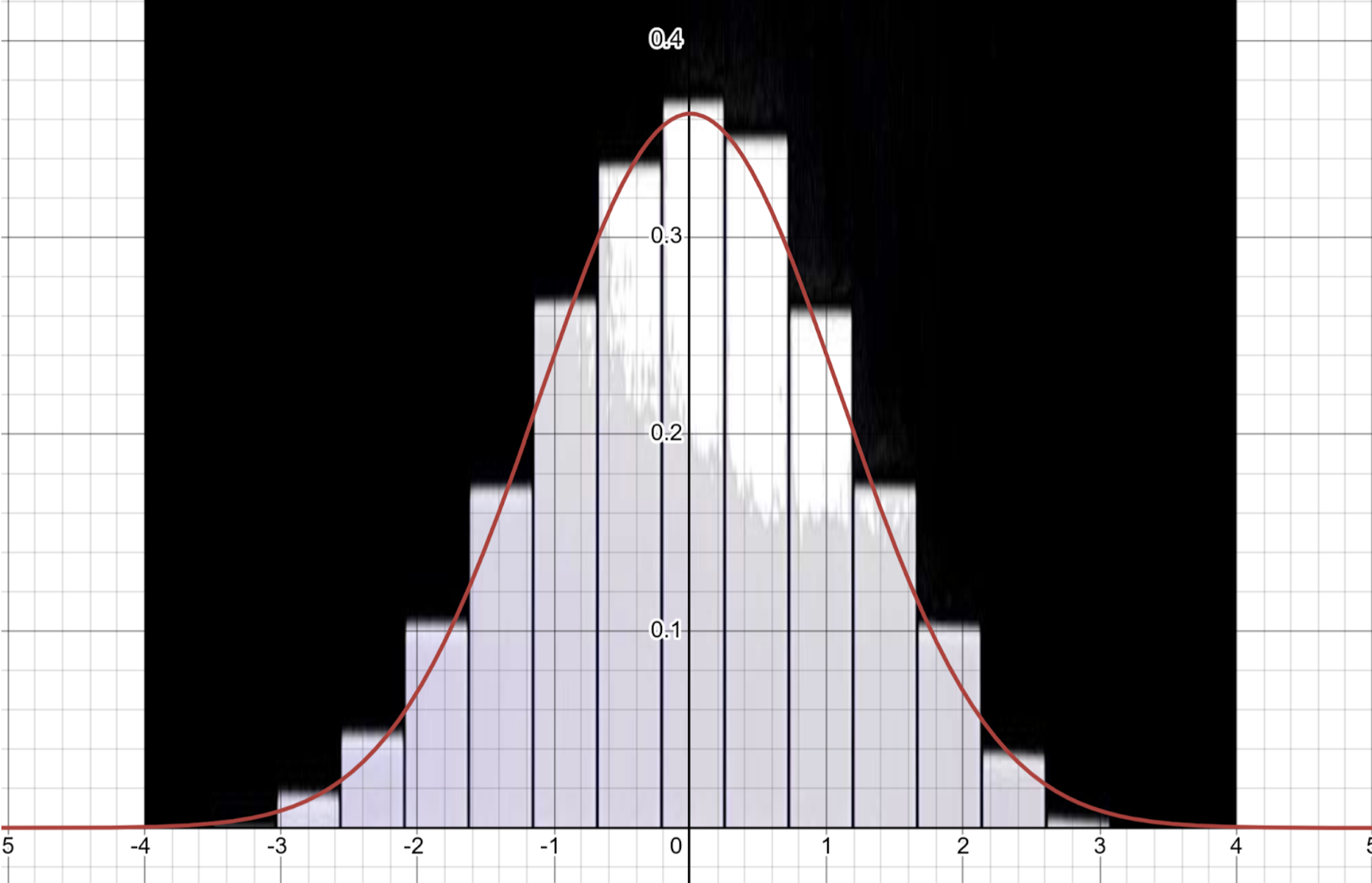
Figure 11: Generated Histogram compared to Ideal Gaussian Distribution
We note that the histogram plot is a very close approximation to the Gaussian distribution. Thus we conclude that the program is indeed doing a good simulation of IID random values. Slight deviations are present in the figure above. This could be down to the relatively low number of trials: The screenshot was taken after 53 seconds of program execution with a total of 58,000 balls. The Gaussian distribution should hold better as the number of balls approaches infinity. Based on the graph, we can conclude that the mean of our Galton Board is around 0.0, with a standard deviation around 2. A theoretical Galton Board which has a middle point at (0,0) also has a mean of 0.0 and a standard deviation of 2. The similar result can prove that the Galton Boards are providing a similar Gaussian with a theoretical standard Galton Board.
Our simulation of the Galton board generates random numbers with finite variance. However, the random numbers are not independent of each other. Ideally, the outcome of each peg collision should be unaffected by previous pegs but this doesn’t hold true for the galton board. Neither is it true that the random values are identically distributed since the bounce-off from a peg is dependent upon the angle and velocity of the initial strike. Still, we are able to see a distribution that approaches the Gaussian. The central limit theorem still holds for systems in which the statistical dependence of past events diminishes sufficiently quickly. In other words, the effect of collision from the first peg decreases rapidly as the ball traverses down row 4, 5, 6, … down to the 16th row. This simulates a “random enough” system that approximates the normal distribution.
Therefore, it is also true that the normal distribution is better approximated with more rows in the galton board. Adding a row to the galton board adds another Bernoulli trial to the system, which generates a quasi-random-enough distribution as we discussed above. The CLT states that the sum of random variables should approach the gaussian as the number of random variables approaches infinity. By increasing the number of random variables, we should better approximate the Gaussian distribution as per the CLT.
Conclusions:
This lab provided valuable insights into real-time digital system design using microcontrollers, reinforcing our understanding of key concepts such as VGA signal generation, PIO programming, and fixed-point arithmetic. The primary objectives of the project were successfully met, demonstrating the ability to create a high-performance simulation within the constraints of the RP2040. In addition to technical skills, we gained practical experience in software optimization, particularly in reducing computational overhead to meet stringent timing deadlines.
Several challenges arose during development, including potentiometer noise, memory limitations, and the difficulty of implementing multi core processing. While we attempted to utilize both cores of the RP2040 for performance improvements, unresolved mutex issues prevented a stable implementation. A major bottleneck was RAM availability, as the majority of system memory was allocated for VGA, leaving limited space for simulation data. Eventually, we hit the maximum memory limit of the RP2040 and could not progress further. Future optimizations could involve restructuring data storage, potentially using fix10 or fix5 data types so save on storage for arithmetic when we know we won’t be utilizing the full range of the fix15 data type.
Despite these constraints, the final implementation successfully simulated up to 5,050 balls in real time while maintaining a smooth visual display and accurate statistical distribution. Overall, this lab was an excellent hands-on exercise in embedded systems programming, signal processing, and performance optimization, providing a strong foundation for future work in digital systems design.
Code
/**
 * Initial framework and libraries by Hunter Adams (vha3@cornell.edu)
 *
 * This demonstration animates two balls bouncing about the screen.
 * Through a serial interface, the user can change the ball color.
 *
 * HARDWARE CONNECTIONS
 *  - GPIO 16 ---> VGA Hsync
 *  - GPIO 17 ---> VGA Vsync
 *  - GPIO 18 ---> 470 ohm resistor ---> VGA Green
 *  - GPIO 19 ---> 330 ohm resistor ---> VGA Green
 *  - GPIO 20 ---> 330 ohm resistor ---> VGA Blue
 *  - GPIO 21 ---> 330 ohm resistor ---> VGA Red
 *  - RP2040 GND ---> VGA GND
 *
 * RESOURCES USED
 *  - PIO state machines 0, 1, and 2 on PIO instance 0
 *  - DMA channels (2, by claim mechanism)
 *  - 153.6 kBytes of RAM (for pixel color data)
 *
 */


// Include the VGA grahics library
#include "vga16_graphics.h"
// Include standard libraries
#include <stdio.h>
#include <stdlib.h>
#include <math.h>
#include <string.h>
// Include Pico libraries
#include "pico/stdlib.h"
#include "pico/divider.h"
#include "pico/multicore.h"
// Include hardware libraries
#include "hardware/pio.h"
#include "hardware/dma.h"
#include "hardware/spi.h"
#include "hardware/clocks.h"
#include "hardware/pll.h"
#include "hardware/adc.h"
// Include protothreads
#include "pt_cornell_rp2040_v1_3.h"


//DMA
// Number of samples per period in sine table
#define sine_table_size 256


// Sine table
int raw_sin[sine_table_size] ;


// Table of values to be sent to DAC
unsigned short DAC_data[sine_table_size] ;


// Pointer to the address of the DAC data table
unsigned short * address_pointer2 = &DAC_data[0] ;


// A-channel, 1x, active
#define DAC_config_chan_A 0b0011000000000000


//SPI configurations
#define PIN_MISO 4
#define PIN_CS   5
#define PIN_SCK  6
#define PIN_MOSI 7
#define SPI_PORT spi0


#define PIN_POT 26
#define PIN_LED 27
#define PIN_BUT 28
#define PIN_BUT_CLR 22


// Number of DMA transfers per event
const uint32_t transfer_count = sine_table_size ;


int data_chan ;
int ctrl_chan ;


int height = 0;
int old_height = 0;


// === the fixed point macros ========================================
typedef signed int fix15 ;
#define multfix15(a,b) ((fix15)((((signed long long)(a))*((signed long long)(b)))>>15))
#define float2fix15(a) ((fix15)((a)*32768.0)) // 2^15
#define fix2float15(a) ((float)(a)/32768.0)
#define absfix15(a) abs(a)
#define int2fix15(a) ((fix15)(a << 15))
#define fix2int15(a) ((int)(a >> 15))
#define char2fix15(a) (fix15)(((fix15)(a)) << 15)
#define divfix(a,b) (fix15)(div_s64s64( (((signed long long)(a)) << 15), ((signed long long)(b))))


// Wall detection
#define hitBottom(b) (b>int2fix15(400))
#define hitTop(b) (b<int2fix15(40))
#define hitLeft(a) (a<int2fix15(0))
#define hitRight(a) (a>int2fix15(640))


// uS per frame
#define FRAME_RATE 33000


// Add after existing #define statements
#define HIST_BOTTOM 480
#define HIST_TOP 420
#define NUM_SLOTS 18
#define MAX_COUNT 50  // Maximum height of histogram in ball counts


// Add after existing defines
#define MIN_BALLS 1
#define MAX_BALLS 5050
#define INITIAL_BALLS 5050


// the color of the boid
char color = WHITE ;


//peg params
fix15 peg_spawn_x = int2fix15(320);
fix15 peg_spawn_y = int2fix15(89);
int r_peg = 6;


fix15 alpha = float2fix15(0.96043387) ;
fix15 beta = float2fix15(0.3978247) ;


fix15 ball_spawn_x = float2fix15(320) ;
fix15 ball_spawn_y = float2fix15(66.0) ;
fix15 ball_spawn_vx = float2fix15(0.0) ;
fix15 ball_spawn_vy = float2fix15(0.0) ;
int r_ball = 2;


fix15 bounciness = float2fix15(0.5) ;
fix15 gravity = float2fix15(0.75) ;


struct ball{
  fix15 x ;
  fix15 y ;
  fix15 vx ;
  fix15 vy ;
  int active;
} ;


struct ball balls[MAX_BALLS];


struct peg{
  fix15 x ;
  fix15 y ;
  int hit ;
} ;


struct peg pegs[136];


int peg_div[21][8] = {
  {0, 1, 2, 3, 4, 5, -1, -1}, // -1 indicates unused slots
  {6, 7, 10, 11, 12, 15, 16, 17},
  {8, 9, 13, 14, 18, 19, 20, -1},
  {21, 22, 23, 28, 29, 30, 31, -1},
  {24, 25, 26, 27, 32, 33, 34, 35},
  {36, 37, 38, 45, 46, 47, -1, -1},
  {39, 40, 41, 48, 49, 50, -1, -1},
  {42, 43, 44, 51, 52, 53, 54, -1},
  {55, 56, 57, 66, 67, 68, -1, -1},
  {58, 59, 60, 69, 70, 71, -1, -1},
  {61, 62, 63, 72, 73, 74, -1, -1},
  {64, 65, 75, 76, 77, -1, -1, -1},
  {78, 79, 80, 91, 92, 93, 94, -1},
  {81, 82, 83, 84, 95, 96, 97, -1},
  {85, 86, 87, 98, 99, 100, 101, -1},
  {88, 89, 90, 102, 103, 104, -1, -1},
  {105, 106, 107, 120, 121, 122, 123, -1},
  {108, 109, 110, 124, 125, 126, -1, -1},
  {111, 112, 113, 127, 128, 129, -1, -1},
  {114, 115, 116, 130, 131, 132, -1, -1},
  {117, 118, 119, 133, 134, 135, -1, -1}
};


// Add after existing global variables
int slot_counts[NUM_SLOTS] = {0};  // Array to track balls in each slot


// Add after existing global variables
int total_balls = 0;     // Total balls that have fallen
int active_balls = 1;    // Current balls being animated (starts with 1)
uint32_t start_time ;     // Store boot time


// Add after existing global variables
static int prev_active = 0;
static int prev_total = -1;
static int prev_time = 0;
static fix15 prev_bounciness = float2fix15(0.0);
static fix15 clrprev_bounciness = float2fix15(0.0);
static fix15 prev_gravity = float2fix15(0.0);
static fix15 clrprev_gravity = float2fix15(0.0);
static int spare_time = 0;
static int prev_spare_time = 0;
static int frames_missed = 0;
static int prev_frames_missed = -1;


// Add after existing global variables
int num_balls = INITIAL_BALLS;
int num_balls_clr = INITIAL_BALLS;


// Add after existing global variables
static int prev_num_balls = INITIAL_BALLS;
static int prev_num_balls_clr = INITIAL_BALLS;
static int initial_ball_count = 0;
static fix15 initial_bounciness = float2fix15(0.0);
static fix15 initial_gravity = float2fix15(0.0);


// Add array to track old heights
int old_heights[NUM_SLOTS] = {0};


//button params
static int debouncer_state = 0;
static int clrdebouncer_state = 0;
static int pot_state = 0;
static int draw_state = 0;


uint16_t low_pass;


void spawnPeg(fix15* x, fix15* y)
{
  //draw peg
  drawCircle(fix2int15(peg_spawn_x), fix2int15(peg_spawn_y), r_peg, WHITE) ;
}


fix15 rand_vx()
{
  return int2fix15(1) - (rand() & 0xffff);
}


// Add new function to draw histogram
void drawHistogram() {
    int slot_width = 38;  // Width of each histogram bar
    int start_x = 35;     // Starting x coordinate (matches leftmost peg)


    int max_height = 0;
    int min_height = 999;  // Initialize to maximum possible value


    // Calculate max_height and min_height for all slots
    for(int i = 0; i < NUM_SLOTS; i++) {
      if(slot_counts[i] > max_height){
        max_height = slot_counts[i];
      }
      if(slot_counts[i] < min_height){
        min_height = slot_counts[i];
      }
    }

    for(int i = 0; i < NUM_SLOTS; i++) {
        int height = ((slot_counts[i] - min_height) * (HIST_BOTTOM - HIST_TOP)) / (max_height - min_height);


            // Clear old bar and draw new one
            if (i == 0) {
                if (height < old_heights[i]){
                fillRect(0, HIST_BOTTOM - old_heights[i], 34, old_heights[i] - height, BLACK);
                }
                else{
                  fillRect(0, HIST_BOTTOM - height, 34, height, WHITE);}
        }
            else if (i == 17) {
                if (height < old_heights[i]){
                fillRect(606, HIST_BOTTOM - old_heights[i], 34, old_heights[i] - height, BLACK);
        }
        else{
                  fillRect(606, HIST_BOTTOM - height, 34, height, WHITE);
                }
            }
            else {
                if (height < old_heights[i]){
                fillRect(start_x + ((i - 1) * slot_width) + 1, HIST_BOTTOM - old_heights[i], slot_width - 2, old_heights[i] - height, BLACK);
                }
                else{
                  fillRect(start_x + ((i - 1) * slot_width) + 1, HIST_BOTTOM - height, slot_width - 2, height, WHITE);
        }
    }
        // Store current height for next comparison
        old_heights[i] = height;
        }


}


// Replace drawString with setTextColor and drawChar for each character
void drawStats() {
    char stats_str[40];
    uint32_t seconds = time_us_32() / 1000000;

    // Set text properties
    setTextColor(WHITE);
    setTextSize(1);
    setTextWrap(0);

    // Clear and update Active count if changed
    if (prev_active != active_balls && (draw_state == 0 || draw_state ==3) ) {
        fillRect(10, 10, 120, 8, BLACK);
        setCursor(10, 10);
        sprintf(stats_str, "Active: %d", active_balls);
        writeString(stats_str);
        prev_active = active_balls;
    }

    // Clear and update Total count if changed
    if (prev_total != total_balls && (draw_state == 1 || draw_state == 4) ) {
        fillRect(10, 20, 120, 8, BLACK);
        setCursor(10, 20);
        sprintf(stats_str, "Total: %d", total_balls);
        writeString(stats_str);
        prev_total = total_balls;
    }

    // Clear and update Time if changed
    if (prev_time != seconds && draw_state == 2) {
        fillRect(10, 30, 120, 8, BLACK);
        setCursor(10, 30);
        sprintf(stats_str, "Time: %d s", (int)seconds);
        writeString(stats_str);
        prev_time = seconds;
    }


    if (prev_bounciness != bounciness && draw_state == 3) {
        fillRect(10, 40, 120, 8, BLACK);
        setCursor(10, 40);
        sprintf(stats_str, "Bounciness: %f", fix2float15(bounciness));
        writeString(stats_str);
        prev_bounciness = bounciness;
    }
    if (prev_gravity != gravity && draw_state == 4) {
      fillRect(10, 50, 120, 8, BLACK);
      setCursor(10, 50);
      sprintf(stats_str, "Gravity: %f", fix2float15(gravity));
      writeString(stats_str);
      prev_gravity = gravity;
    }
    if (prev_spare_time != spare_time && draw_state == 5) {
        fillRect(10, 60, 120, 8, BLACK);
        setCursor(10, 60);
        sprintf(stats_str, "Spare: %d us", spare_time);
        writeString(stats_str);
        prev_spare_time = spare_time;
    }
    if (draw_state == 5){
      draw_state = 0;
    } else {
      draw_state++;
    }
}


void pegCollision(fix15* bx, fix15* by, fix15* bvx, fix15* bvy, fix15* px, fix15* py)
{
  fix15 dx = *bx - *px ;
  fix15 dy = *by - *py ;


  fix15 abs_dx = (dx < int2fix15(0)) ? multfix15( dx , float2fix15(-1.0) ) : dx ;
  fix15 abs_dy = (dy < int2fix15(0)) ? multfix15( dy , float2fix15(-1.0) ) : dy ;


  if ( (abs_dx < int2fix15(r_ball + r_peg) ) && (abs_dy < int2fix15(r_ball + r_peg) ) ){
    //DMA popping noise
    if (!dma_channel_is_busy(data_chan)) {
      dma_channel_set_read_addr(data_chan, DAC_data, false) ;
      dma_start_channel_mask(1u << data_chan) ;
    }
    fix15 distance ;
    fix15 max = (abs_dx > abs_dy) ? abs_dx : abs_dy ;
    fix15 min = (abs_dx < abs_dy) ? abs_dx : abs_dy ;
    // float interm1 = (float) sqrt( (double) fix2float15(multfix15(dx, dx) + multfix15(dy, dy) )) ;
    distance = multfix15( max , alpha ) + multfix15( min , beta ) ;

    fix15 normalx = divfix(dx, distance) ;
    fix15 normaly = divfix(dy, distance) ;

    fix15 intermediate_term = multfix15( float2fix15(-2.0) , (multfix15(normalx, *bvx) + multfix15(normaly, *bvy)) ) ;

    if (intermediate_term > int2fix15(0)) {
      // printf('\nhere') ;
      *bx = *px + (multfix15(normalx , (distance + int2fix15(1) ) ) ) ;
      *by = *py + (multfix15(normaly , (distance + int2fix15(1) ) ) ) ;


      *bvx = *bvx + multfix15(normalx , intermediate_term) ;
      *bvy = *bvy + multfix15(normaly , intermediate_term) ;

      *bvx = multfix15(bounciness , *bvx ) ;
      *bvy = multfix15(bounciness , *bvy ) ;
    }
  }
}


// Modify ballUpdate function
void ballUpdate(fix15* bx, fix15* by, fix15* bvx, fix15* bvy) {
    if (hitBottom(*by)) {
        total_balls++;
        int x_pos = fix2int15(*bx);
        int slot;


        if (x_pos < 35) {
            slot = 0;
        } else if (x_pos > 605) {
            slot = 17;
        } else {
            slot = ((x_pos - 35) / 38) + 1;
        }
        if (slot >= 0 && slot < NUM_SLOTS) {
            slot_counts[slot]++;
        }


        // Reset ball position
        *bx = ball_spawn_x;
        *by = ball_spawn_y;
        *bvx = rand_vx();
        *bvy = ball_spawn_vy;
    } else {
        if (hitRight(*bx)) {
            *bvx = (-*bvx);
            *bx  = (*bx - int2fix15(5));
        }
        if (hitLeft(*bx)) {
            *bvx = (-*bvx);
            *bx  = (*bx + int2fix15(5));
        }
        if (hitTop(*by)) {
            *bvy = (-*bvy);
            *by  = (*by + int2fix15(5));
        }


        // Apply gravity
        *bvy = *bvy + gravity;

        // Update position using velocity
        *bx = *bx + *bvx;
        *by = *by + *bvy;
    }
}


// Add function to read potentiometer
void read_potentiometer() {
    // Read ADC and convert to voltage
    uint16_t raw = adc_read();
    low_pass = low_pass + ((raw - low_pass) >> 7 );
    //const float conversion_factor = 3.3f / (1 << 12);
    //float voltage = low_pass * conversion_factor;

    if (pot_state == 0){
      //reset
      fillRect(4, 50, 4, 8, BLACK);
    } else if (pot_state == 1){
      // Calculate ball count (1-1000)
      fillRect(4, 10, 4, 8, GREEN);
      prev_num_balls_clr = num_balls;
      int new_balls = 1 + (low_pass * (MAX_BALLS-1)) / 4096;
      if (initial_ball_count == 0){
        initial_ball_count = new_balls;
      }
      if (abs(new_balls - initial_ball_count) >50){
        //above threshold, draw histogram
        for (int i = 0; i < NUM_SLOTS; ++i) {
        slot_counts[i] = 0;
        old_heights[i] = 0;  // Reset old heights
        }
        total_balls = 0;      // Reset total balls
        prev_total = -1;      // Force stats update
        fillRect(0, 420, 640, 60, BLACK);
        initial_ball_count = new_balls;
      }
      num_balls = new_balls;
    } else if (pot_state == 2){
      // Calculate bounciness (0.0-1.0)
      fillRect(4, 10, 4, 8, BLACK);
      fillRect(4, 40, 4, 8, GREEN);
      fix15 new_bounciness = float2fix15(low_pass / 4096.0);

      // On first entry to this state
      if (initial_bounciness == 0) {
          initial_bounciness = new_bounciness;
      }

      // Check total change from initial value
      if (abs(initial_bounciness - new_bounciness) > float2fix15(0.05)) {
          for (int i = 0; i < NUM_SLOTS; ++i) {
              slot_counts[i] = 0;
              old_heights[i] = 0;
          }
          total_balls = 0;
          prev_total = -1;
          fillRect(0, 420, 640, 60, BLACK);
          initial_bounciness = new_bounciness;
      }
      bounciness = new_bounciness;
  }
  else {
      // Calculate gravity (0.0-1.0)
      fillRect(4, 40, 4, 8, BLACK);
      fillRect(4, 50, 4, 8, GREEN);
      fix15 new_gravity = float2fix15(low_pass / 4096.0);

      // On first entry to this state
      if (initial_gravity == 0) {
          initial_gravity = new_gravity;
      }

      // Check total change from initial value
      if (abs(initial_gravity - new_gravity) > float2fix15(0.05)) {
          for (int i = 0; i < NUM_SLOTS; ++i) {
              slot_counts[i] = 0;
              old_heights[i] = 0;
          }
          total_balls = 0;
          prev_total = -1;
          fillRect(0, 420, 640, 60, BLACK);
          initial_gravity = new_gravity;
      }
      gravity = new_gravity;
  }
}


void read_button() {
  int input = gpio_get(PIN_BUT);


  if (debouncer_state == 0) { //not pressed
    debouncer_state = ( input == 0 ) ? 1 : 0 ;
  }
  else if (debouncer_state == 1) { //maybe pressed
    if (input == 0) {
      debouncer_state = 2;
      //cycle through pot_state:
      //0 -> # of balls
      //1 -> bounciness
      //2 -> gravity
      pot_state = (pot_state == 3) ? 0 : pot_state + 1 ;
    } else {
      debouncer_state = 0;
    }
  } else if (debouncer_state == 2) { //pressed
    debouncer_state = ( input == 1 ) ? 3 : 2 ;
  } else { //maybe not pressed
    debouncer_state = ( input == 1 ) ? 0 : 2 ;
  }
}


void read_clrbutton() {
  int input = gpio_get(PIN_BUT_CLR);


  if (clrdebouncer_state == 0) { //not pressed
    clrdebouncer_state = ( input == 0 ) ? 1 : 0 ;
  }
  else if (clrdebouncer_state == 1) { //maybe pressed
    if (input == 0) {
      clrdebouncer_state = 2;
      //clear histogram and total ball number
      //clear histogram and total ball number
      for (int i = 0; i < NUM_SLOTS; ++i) {
        slot_counts[i] = 0;
        old_heights[i] = 0;  // Reset old heights
      }
      total_balls = 0;      // Reset total balls
      prev_total = -1;      // Force stats update


      printf("clearing histogram\n");


      // Clear histogram area
      fillRect(0, 420, 640, 60, BLACK);
    } else {
      clrdebouncer_state = 0;
    }
  } else if (clrdebouncer_state == 2) { //pressed
    clrdebouncer_state = ( input == 1 ) ? 3 : 2 ;
  } else { //maybe not pressed
    clrdebouncer_state = ( input == 1 ) ? 0 : 2 ;
  }
}


void drawFastCircle_r1(short x0, short y0, char color){
  drawPixel(x0 , y0, color);
  drawPixel(x0  , y0+1, color);
  drawPixel(x0  , y0-1, color);
  drawPixel(x0+1, y0  , color);
  drawPixel(x0-1, y0  , color);
}


int return_peg_div_indx(fix15 x, fix15 y){
  if (y < float2fix15 (136.5)){
    return 0;
  } else if (y < float2fix15(193.5)){
    if (x < float2fix15(329.5)){
      return 1;
    } else {
      return 2;
    }
  } else if (y < float2fix15(231.5)){
    if (x < float2fix15(310.5)){
      return 3;
    } else {
      return 4;
    }
  } else if (y < float2fix15(269.5)){
    if (x < float2fix15(253.5)){
      return 5;
    } else if (x < float2fix15(367.5)){
      return 6;
    } else {
      return 7;
    }
  } else if (y < float2fix15(307.5)){
    if (x < float2fix15(215.5)){
      return 8;
    } else if (x < float2fix15(329.5)){
      return 9;
    }
    else if (x < float2fix15(443.5)){
      return 10;
    } else {
      return 11;
    }
  } else if (y < float2fix15(343.5)){
    if (x < float2fix15(196.5)){
      return 12;
    } else if (x < float2fix15(329.5)){
      return 13;
    } else if (x < float2fix15(462.5)){
      return 14;
    } else {
      return 15;
    }
  } else {
    if (x < float2fix15(158.5)){
      return 16;
    } else if (x < float2fix15(272.5)){
      return 17;
    } else if (x < float2fix15(386.5)){
      return 18;
    } else if (x < float2fix15(500.5)){
      return 19;
    } else {
      return 20;
    }
  }
}


// Update animation thread
static PT_THREAD (protothread_anim(struct pt *pt)) {
    // Mark beginning of thread
    PT_BEGIN(pt);


    // Variables for maintaining frame rate
    static int begin_time ;
    //static int spare_time ;


    start_time = time_us_32() ;  // Store boot time


    static int input_iters = 0;


    while(1) {
      // Measure time at start of thread
      begin_time = time_us_32() ;

      read_button();
      read_potentiometer();
      read_clrbutton();

      // Clear all balls if count changes
      if (prev_num_balls != num_balls) {
          for (int ball = num_balls ; ball < MAX_BALLS ; ball++) {
              drawFastCircle_r1(fix2int15(balls[ball].x), fix2int15(balls[ball].y), BLACK);
          }
          prev_num_balls = num_balls;
      }

      // Track active balls
      active_balls = 0;


      // For each ball
      for (int ball = 0; ball < num_balls; ball++) {
        // Check if the ball is within the screen boundaries
        if (fix2int15(balls[ball].y) <= 400) {
          active_balls++;
        }


        // erase ball at current position
        drawFastCircle_r1(fix2int15(balls[ball].x), fix2int15(balls[ball].y), BLACK);


        int peg_indx = return_peg_div_indx(balls[ball].x, balls[ball].y);
        for (int i = 0; i < 8; i++) {
          pegCollision(&balls[ball].x, &balls[ball].y, &balls[ball].vx, &balls[ball].vy, &pegs[peg_div[peg_indx][i]].x, &pegs[peg_div[peg_indx][i]].y);
        }

        ballUpdate(&balls[ball].x, &balls[ball].y, &balls[ball].vx, &balls[ball].vy) ;

        // draw the boid at its new position
        drawFastCircle_r1(fix2int15(balls[ball].x), fix2int15(balls[ball].y), BLUE);
      }


      // Draw all pegs
      for (int i = 0; i < 136; i++) {
        drawCircle(fix2int15(pegs[i].x), fix2int15(pegs[i].y), r_peg, WHITE);
      }


      // Draw histogram after drawing pegs
      drawHistogram();


      // Draw stats after arena but before other elements
      drawStats();


      // delay in accordance with frame rate
      spare_time = FRAME_RATE - (time_us_32() - begin_time) ;
      if (spare_time < 0) {
          gpio_put(PIN_LED, 1);
      }
      else {
          gpio_put(PIN_LED, 0);
      }


      //benchmark
      if ( (start_time + 30  <  (time_us_32() / 1000000) < start_time + 40 ) && (spare_time < 0) )  {
        frames_missed++ ;
      }
      // yield for necessary amount of time
      PT_YIELD_usec(spare_time) ;
     // NEVER exit while
    } // END WHILE(1)
  PT_END(pt);
} // animation thread


// ========================================
// === core 1 main -- started in main below
// ========================================
// void core1_main(){
//   // Add animation thread
//   pt_add_thread(protothread_anim1);
//   // Start the scheduler
//   pt_schedule_start ;
// }


// ========================================
// === main
// ========================================
// USE ONLY C-sdk library
int main(){
  // initialize stio
  stdio_init_all() ;


  set_sys_clock_khz(250000, true);

  // Initialize SPI channel (channel, baud rate set to 20MHz)
  spi_init(SPI_PORT, 20000000) ;


  // Format SPI channel (channel, data bits per transfer, polarity, phase, order)
  spi_set_format(SPI_PORT, 16, 0, 0, 0);


  // Map SPI signals to GPIO ports, acts like framed SPI with this CS mapping
  gpio_set_function(PIN_MISO, GPIO_FUNC_SPI);
  gpio_set_function(PIN_CS, GPIO_FUNC_SPI) ;
  gpio_set_function(PIN_SCK, GPIO_FUNC_SPI);
  gpio_set_function(PIN_MOSI, GPIO_FUNC_SPI);


  // LED indicator for missed timing
  gpio_init(PIN_LED) ;
  gpio_set_dir(PIN_LED, GPIO_OUT) ;
  gpio_put(PIN_LED, 0) ;


  //Button GPIO
  gpio_init(PIN_BUT) ;
  gpio_set_dir(PIN_BUT, GPIO_IN) ;
  gpio_pull_up(PIN_BUT) ;
  gpio_init(PIN_BUT_CLR);
  gpio_set_dir(PIN_BUT_CLR, GPIO_IN);
  gpio_pull_up(PIN_BUT_CLR);


  // Build sine table and DAC data table
  int i ;
  for (i=0; i<(sine_table_size); i++){
      raw_sin[i] = (int)(2047 * sin((float)i*6.283/(float)sine_table_size) + 2047); //12 bit
      DAC_data[i] = DAC_config_chan_A | (raw_sin[i] & 0x0fff) ;
  }


  // Select DMA channels
  data_chan = dma_claim_unused_channel(true);;
  ctrl_chan = dma_claim_unused_channel(true);;


  // Setup the control channel
  dma_channel_config c = dma_channel_get_default_config(ctrl_chan);   // default configs
  channel_config_set_transfer_data_size(&c, DMA_SIZE_32);             // 32-bit txfers
  channel_config_set_read_increment(&c, false);                       // no read incrementing
  channel_config_set_write_increment(&c, false);                      // no write incrementing
  channel_config_set_chain_to(&c, data_chan);                         // chain to data channel


  dma_channel_configure(
      ctrl_chan,                          // Channel to be configured
      &c,                                 // The configuration we just created
      &dma_hw->ch[data_chan].read_addr,   // Write address (data channel read address)
      &address_pointer2,                   // Read address (POINTER TO AN ADDRESS)
      1,                                  // Number of transfers
      false                               // Don't start immediately
  );


  // Setup the data channel
  dma_channel_config c2 = dma_channel_get_default_config(data_chan);  // Default configs
  channel_config_set_transfer_data_size(&c2, DMA_SIZE_16);            // 16-bit txfers
  channel_config_set_read_increment(&c2, true);                       // yes read incrementing
  channel_config_set_write_increment(&c2, false);                     // no write incrementing
  // (X/Y)*sys_clk, where X is the first 16 bytes and Y is the second
  // sys_clk is 125 MHz unless changed in code. Configured to ~44 kHz
  dma_timer_set_fraction(0, 0x0017, 0xffff) ;
  // 0x3b means timer0 (see SDK manual)
  channel_config_set_dreq(&c2, 0x3b);                                 // DREQ paced by timer 0
  // chain to the controller DMA channel
  // channel_config_set_chain_to(&c2, ctrl_chan);                        // Chain to control channel


  dma_channel_configure(
      data_chan,                  // Channel to be configured
      &c2,                        // The configuration we just created
      &spi_get_hw(SPI_PORT)->dr,  // write address (SPI data register)
      DAC_data,                   // The initial read address
      sine_table_size,            // Number of transfers
      false                       // Don't start immediately.
  );


  int peg_positions_x[136] = {
    320,
    301, 339,
    282, 320, 358,
    263, 301, 339, 377,
    244, 282, 320, 358, 396,
    225, 263, 301, 339, 377, 415,
    206, 244, 282, 320, 358, 396, 434,
    187, 225, 263, 301, 339, 377, 415, 453,
    168, 206, 244, 282, 320, 358, 396, 434, 472,
    149, 187, 225, 263, 301, 339, 377, 415, 453, 491,
    130, 168, 206, 244, 282, 320, 358, 396, 434, 472, 510,
    111, 149, 187, 225, 263, 301, 339, 377, 415, 453, 491, 529,
     92, 130, 168, 206, 244, 282, 320, 358, 396, 434, 472, 510, 548,
     73, 111, 149, 187, 225, 263, 301, 339, 377, 415, 453, 491, 529, 567,
     54,  92, 130, 168, 206, 244, 282, 320, 358, 396, 434, 472, 510, 548, 586,
     35,  73, 111, 149, 187, 225, 263, 301, 339, 377, 415, 453, 491, 529, 567, 605
  };


  int peg_positions_y[136] = {
    89,
    108, 108,
    127, 127, 127,
    146, 146, 146, 146,
    165, 165, 165, 165, 165,
    184, 184, 184, 184, 184, 184,
    203, 203, 203, 203, 203, 203, 203,
    222, 222, 222, 222, 222, 222, 222, 222,
    241, 241, 241, 241, 241, 241, 241, 241, 241,
    260, 260, 260, 260, 260, 260, 260, 260, 260, 260,
    279, 279, 279, 279, 279, 279, 279, 279, 279, 279, 279,
    298, 298, 298, 298, 298, 298, 298, 298, 298, 298, 298, 298,
    317, 317, 317, 317, 317, 317, 317, 317, 317, 317, 317, 317, 317,
    336, 336, 336, 336, 336, 336, 336, 336, 336, 336, 336, 336, 336, 336,
    355, 355, 355, 355, 355, 355, 355, 355, 355, 355, 355, 355, 355, 355, 355,
    374, 374, 374, 374, 374, 374, 374, 374, 374, 374, 374, 374, 374, 374, 374, 374
  };


  for (int i = 0; i < 136; i++){
    pegs[i].x = int2fix15(peg_positions_x[i]);
    pegs[i].y = int2fix15(peg_positions_y[i]);
  }


    for (int i = 0; i < MAX_BALLS; i++){
    balls[i].x = ball_spawn_x ;
    balls[i].y = ball_spawn_y ;
    balls[i].vx = rand_vx() ;
    balls[i].vy = ball_spawn_vy ;
  }


  // Initialize ADC
  adc_init();
  // Make sure GPIO is high-impedance, no pullups etc
  adc_gpio_init(PIN_POT);
  // Select ADC input 0 (GPIO 26)
  adc_select_input(0);


  //initialize low_pass filter
  low_pass = adc_read();


  // Exit main.
  // No code executing!!


  // initialize VGA
  initVGA() ;


  // start core 1
  // multicore_reset_core1();
  // multicore_launch_core1(&core1_main);


  // add threads
  // pt_add_thread(protothread_serial);
  pt_add_thread(protothread_anim);


  // start scheduler
  pt_schedule_start ;
}