
Fast Robots - Lab 12: Path Planning and Execution
This lab is a culmination of all of the previous labs coming together. The goal of this lab is to have the robot navigate through a set of waypoints in that environment as quickly and accurately as possible.
An uphill battle
Due to a mix of unfortunate accidents and extenuating circumstances, a great deal of time was spent on step 0: getting everything that should already be working to work again. The first issue I tried to fix was my left motor driver. Despite correct pwm output and continuity with my signal and power pins to my left motor driver, it would refuse to spin. Thus, I resoldered everything. Twice. And it still didn’t work. Then I gave up for the night, came back the next day and it just started working again after changing nothing.
Electromagnetism?! idk
Next, my TOF sensor was giving me incredibly noisy and unreliable data. Sometimes it would work perfect and othertimes it would freak out. After close inspection, it seems like the front part had cracked. I don’t know when this happened, but if I had to guess, it was likely during the stunt performance on ECE Robotics day. My other ToF sensor is also broken so this puts me in a difficult position for this lab.
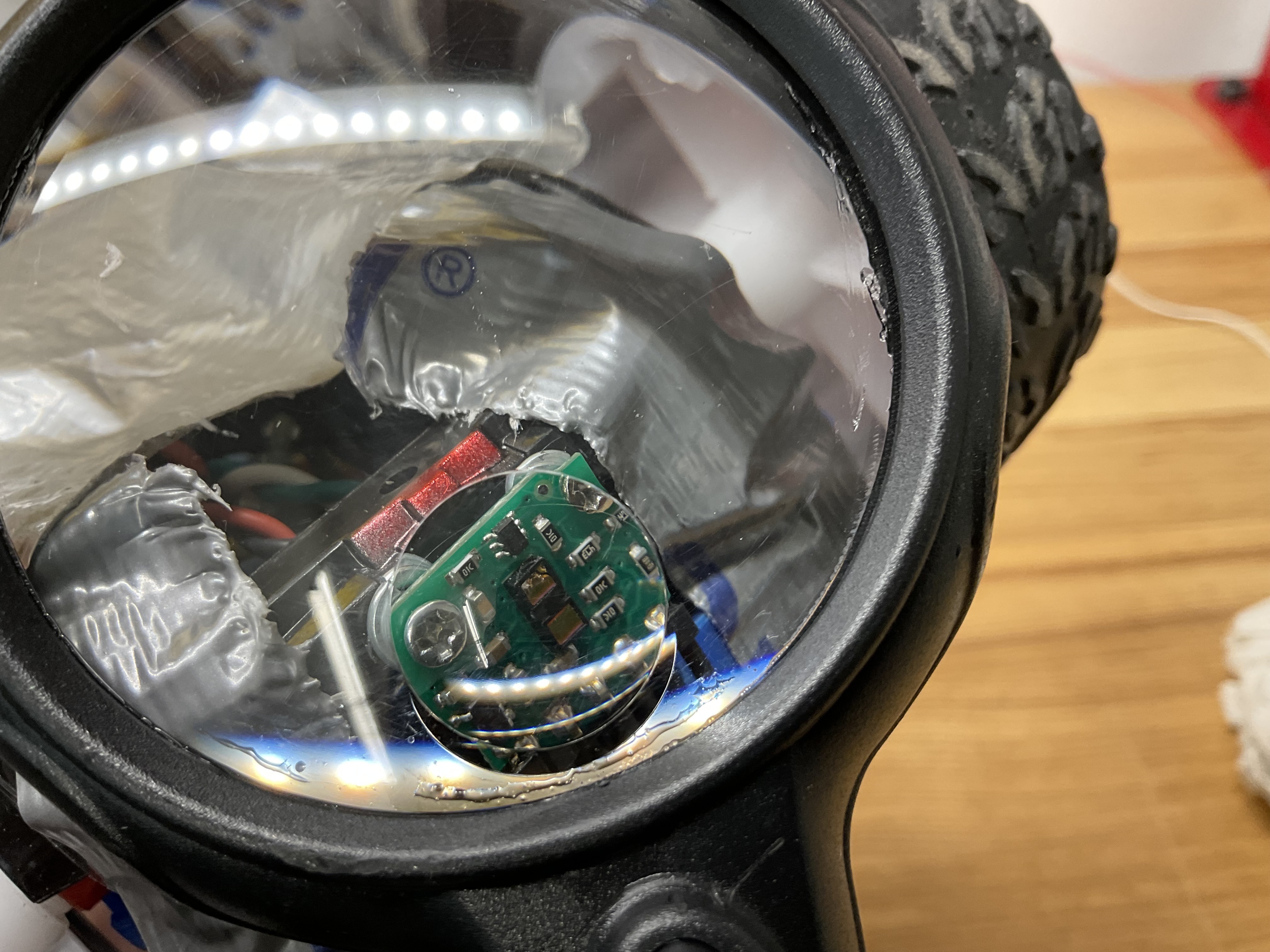

My ToF Sensor and my reaction upon learning of its demise
Thus, I had to get creative to navigate through the waypoints.
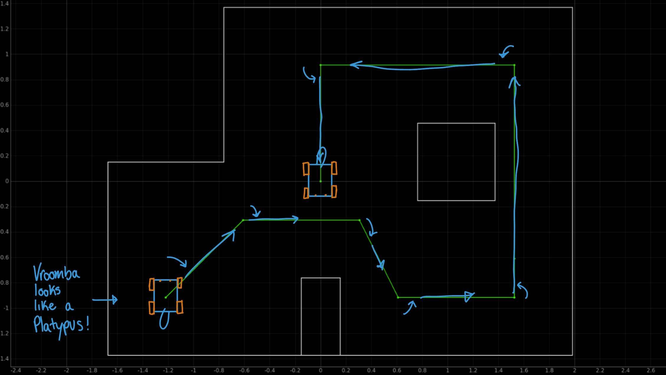
Waypoint Test Plan
Angular PID Control Revamp
After testing my newly soldered motor drivers, I found that my robot was behaving significantly different from the earlier lab this semester. I suspect some components or gears in the drivetrain wore down over time and there’s less internal resistance so I can turn at a much lower PWM value. This is actually good news since I can have a much less jerky system now. I also implemented the ability to write new target angles remotely and tuned for new k values.
After tuning, I also removed the data collection component since it took a very long time to send.
t= 45
ble.send_command(CMD.PID_A_BEGIN, f'{t}')
    case PID_A_BEGIN:
      {
        icm_20948_DMP_data_t data;
        myICM.readDMPdataFromFIFO(&data);
        delay(2000);
        int count = 0;
        int distance = 0;
        int target = 0;
        int pwm = 0;
        int dir = 0;
        int err = 0;
        float errI = 0;
        float errP = 0;
        float errD = 0;
        float errOld = 0;
        int success=0;
        int ang_target=0;
        bool loop=1;
        int fin=0;
        float pid_dt = 0;


        success = robot_cmd.get_next_value(ang_target);
        if (!success)
          return;
        target=ang_target;

        while (loop == 1) {

          icm_20948_DMP_data_t data;
          myICM.readDMPdataFromFIFO(&data);
          if ((myICM.status == ICM_20948_Stat_Ok) || (myICM.status == ICM_20948_Stat_FIFOMoreDataAvail))  // Was valid data available?
          {
            if ((data.header & DMP_header_bitmap_Quat6) > 0)  // We have asked for GRV data so we should receive Quat6
            {
              double q1 = ((double)data.Quat6.Data.Q1) / 1073741824.0;  // Convert to double. Divide by 2^30
              double q2 = ((double)data.Quat6.Data.Q2) / 1073741824.0;  // Convert to double. Divide by 2^30
              double q3 = ((double)data.Quat6.Data.Q3) / 1073741824.0;  // Convert to double. Divide by 2^30
              double q0 = sqrt(1.0 - ((q1 * q1) + (q2 * q2) + (q3 * q3)));
              double qw = q0;
              double qx = q2;
              double qy = q1;
              double qz = -q3;
              double t3 = +2.0 * (qw * qz + qx * qy);
              double t4 = +1.0 - 2.0 * (qy * qy + qz * qz);
              double yaw = atan2(t3, t4) * 180.0 / PI;
              ////////////////////////////////////////////////////////////////////////////////PID CONTROL+

              unsigned long now = micros();
              pid_dt = (now - prevTimePID)*1e-6f;  // secs
              prevTimePID = now;

              errP = yaw - target;
              if      (errP >  180) errP -= 360;
              else if (errP < -180) errP += 360;

              errI += errP * pid_dt;
              if      (errI >  150) errI =  150;
              else if (errI < -150) errI = -150;

              if (pid_dt > 0) {
                errD = (errP - errOld)/pid_dt;
              }
              errOld = errP;

              err = (float)errP + errI + errD;

              pwm = (int) kp_a*errP + ki_a*errI + kd_a*errD;


              if (err > 0) {
                //turn clockwise
                dir = 1;
              }

              else if (err < 0) {
                // turn c clockwise
                dir = (-1);
              }
              pwm = abs(pwm);

              if (pwm < pwmMinA) {
                pwm = pwmMinA;
              }
              if (pwm > pwmMax) {
                pwm = pwmMax;
              }

              if (abs(err) < (1)) {
                pwm = 0;
                fin = fin+1;
                if (fin>30){
                  loop=0;
                }
              }
              count++;
              turn(dir, pwm);

            }
          }

          if (myICM.status != ICM_20948_Stat_FIFOMoreDataAvail)  // If more data is available then we should read it right away - and not delay
          {
            delay(10);
          }
        }

        analogWrite(motor1a, 0);
        analogWrite(motor1b, 0);

        analogWrite(motor2a, 0);
        analogWrite(motor2b, 0);

        tx_estring_value.clear();
        tx_estring_value.append(count);
        tx_estring_value.append(" | ");
        tx_estring_value.append(loop);
        tx_estring_value.append(" | ");
        tx_estring_value.append(fin);

        tx_characteristic_string.writeValue(tx_estring_value.c_str());

        break;
      }
After tuning the system, I was able to change the position of the robot from my robot. However, with broken ToF sensors, I can’t use my linear PID. Thus I decided to rewrite my old BLE_Drive case and tune the distances manually. This was somewhat tedious, but the result ended up being very promising. This sped up my test time considerably. This was especially impactful with limited testing space and when other student would run their whole robot with the localization sequence, the space would be occupied for upwards of 10 minutes at a time. With my set up, I was able to achieve often better results in fraction of the time. In my case, there would still be variablity with varying battery voltages affecting performance, but overall, the system is simple, effective, and efficient; working signifigantly better than anticpating consider the various disasters and hinderances I’m working around.
    case BLE_DRIVE:
      {
        float pwm1, pwm2, pwm3;
        float dir1, dir2, dir3;
        float time1, time2, time3;

        success = robot_cmd.get_next_value(pwm1); if(!success) return;
        success = robot_cmd.get_next_value(dir1); if(!success) return;
        success = robot_cmd.get_next_value(time1); if(!success) return;

        success = robot_cmd.get_next_value(pwm2); if(!success) return;
        success = robot_cmd.get_next_value(dir2); if(!success) return;
        success = robot_cmd.get_next_value(time2); if(!success) return;

        success = robot_cmd.get_next_value(pwm3); if(!success) return;
        success = robot_cmd.get_next_value(dir3); if(!success) return;
        success = robot_cmd.get_next_value(time3); if(!success) return;

        driveStraight(dir1, pwm1);
        delay((unsigned long)time1);
        driveStraight(dir2, pwm2);
        delay((unsigned long)time2);
        driveStraight(dir3, pwm3);
        delay((unsigned long)time3);

        analogWrite(motor1a, 0);
        analogWrite(motor1b, 0);
        analogWrite(motor2a, 0);
        analogWrite(motor2b, 0);
        break;
      }
pwm1, dir1, time1 = 155, 1, 600
pwm2, dir2, time2 = 245, -1, 200
pwm3, dir3, time3 =   0, 1, 300

ble.send_command(
    CMD.BLE_DRIVE,
    f"{pwm1}|{dir1}|{time1}|"
    f"{pwm2}|{dir2}|{time2}|"
    f"{pwm3}|{dir3}|{time3}"
)
Drive Code
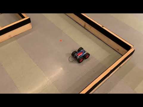
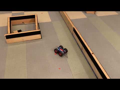
Robot in Action
Acknowledgements
I worked alone on this lab, but I am incredibly thankful to the support of the TAs and course staff. Throughout the semester, I got help from Kelvin Resch, Rachel Arena, and Selena Yao. I also referenced Nila Narayan’s and Bhadja Bejoy’s past course websites for inspiration or aide when I was stuck or lost. Their sites were done very well.
This class was much more work than anticipated, but worthwhile. One of the hardest classes I’ve taken here, but it was fun and I learned a ton. Would reccomend to future engineering students.