
Fast Robots - Lab 4: Motor Drivers & Open Loop Control
Prelab
Motor Driver Wiring
I began by wiring the H-Bridge motor drivers according to the datasheet, ensuring each pin was correctly connected. My previous wiring diagram from Lab 3 contained an error—it used the VMM pins, which do not serve a functional purpose. Below is the corrected wiring setup:
Circuit Diagram:
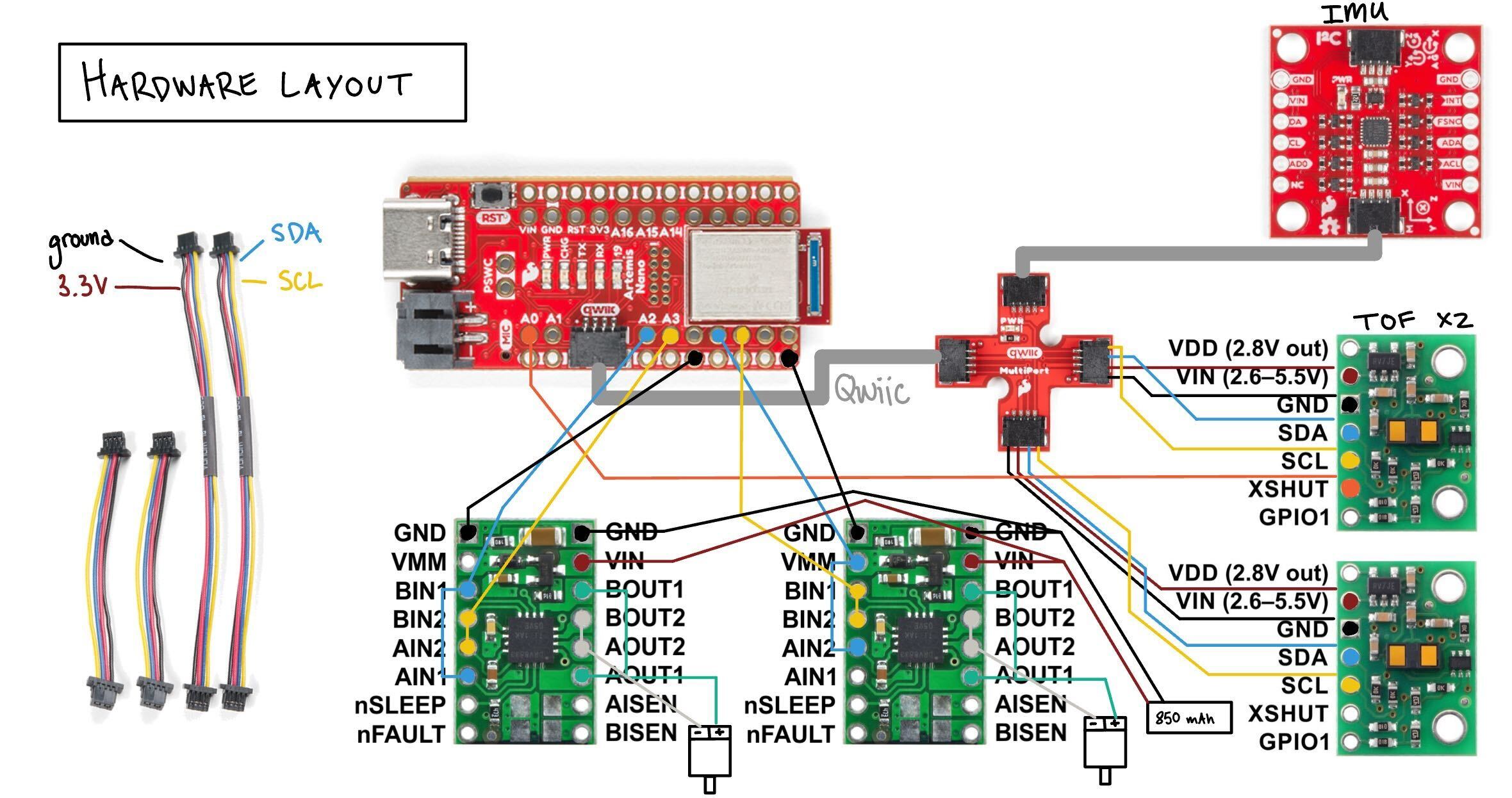
Figure 1: Updated wiring diagram
The A and B input/output pins were coupled to provide sufficient current to the motors. Each board powers one motor, which in turn drives two wheels. Without daisy-chaining the pins, the current would be halved, reducing motor performance.
Battery Discussion
Each motor driver and the Artemis are powered separately by 650 mAh batteries. The motors require significantly more current than the Artemis, and separate power paths reduce signal noise.
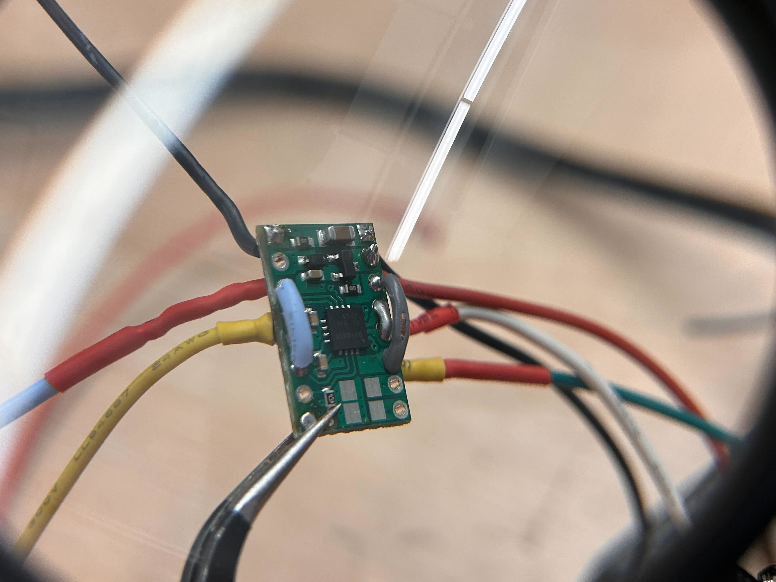
Figure 2: Soldered Motor Driver
PWM Tests
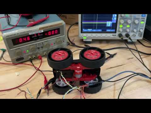
Before soldering my drivers to the motors, I tested the motor drivers to verify bidirectional functionality. Applying HIGH to one input and LOW to the other should drive the motor in either direction.
I supplied 3.7V to the drivers, although they accept up to 10V. The OUT1 and OUT2 pins were probed using an oscilloscope while running a PWM loop. I referenced code from Bhadra Bejoy (2023) to increment the PWM from 0 to 255.
#define motor1a 2
#define motor1b 3

#define motor2a 5
#define motor2b 6


void setup() {
  Serial.begin(115200);
  pinMode(motor1a, OUTPUT);
  pinMode(motor1b, OUTPUT);
  analogWrite(motor1a,0);
  analogWrite(motor1b,0);

  pinMode(motor2a, OUTPUT);
  pinMode(motor2b, OUTPUT);
  analogWrite(motor2a,0);
  analogWrite(motor2b,0);
  delay(15000);
}

void loop() {

  for (int i = 0; i < 15; i++) {
    //right wheels
    analogWrite(motor1a,i);
    delay(200);

  }
}
PWM incrementing test code
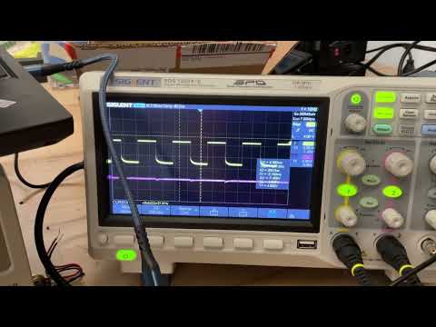
Motor Driver 1 PWM Test
Motor Driver 2 PWM Test
Testing Individual Motors
After soldering, I confirmed that each motor functioned properly by applying power and running the following test script:
#define motor1a 2
#define motor1b 3

#define motor2a 5
#define motor2b 6


void setup() {
  Serial.begin(115200);
  pinMode(motor1a, OUTPUT);
  pinMode(motor1b, OUTPUT);
  analogWrite(motor1a,0);
  analogWrite(motor1b,0);

  pinMode(motor2a, OUTPUT);
  pinMode(motor2b, OUTPUT);
  analogWrite(motor2a,0);
  analogWrite(motor2b,0);
  delay(5000);
}

void loop() {

    analogWrite(motor1a,200);
    analogWrite(motor2b,0);
    delay(1000);

    analogWrite(motor1a,0);
    analogWrite(motor2b,200);
    delay(1000);
}
Figure 3: Motor verification code
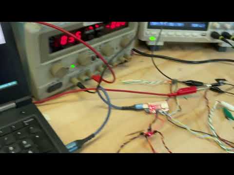
Motor unloaded test
Open Loop Control
Installation
I integrated all components, ensuring braided cables to reduce noise and securing wires with tape. I mounted one TOF sensor in the front and one in the side.
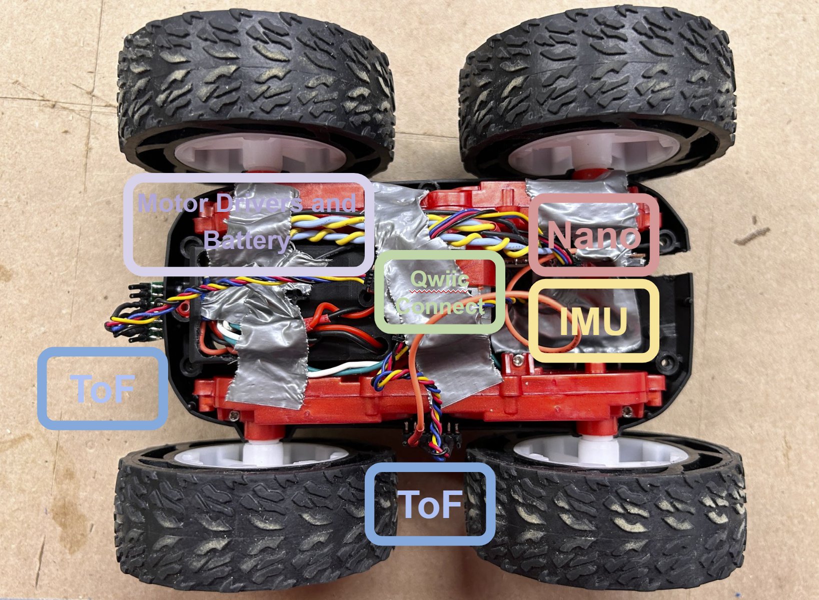
Figure 4: Fully wired robot
System Drift
To evaluate drift, I ran the robot foward, varying time and PWM signal around a dozen times
Adding a Calibration Constant
To compensate for drift, I introduced a calibration factor to adjust the left motor’s PWM. I manually tuned this value through trial and error. The final calibration factor was 0.82, which significantly reduced drift.
#define motor1a 2
#define motor1b 3
#define m1pwm 45


#define motor2a 5
#define motor2b 6
#define m2pwm 55


void setup() {
  Serial.begin(115200);
  pinMode(motor1a, OUTPUT);
  pinMode(motor1b, OUTPUT);
  analogWrite(motor1a,0);
  analogWrite(motor1b,0);

  pinMode(motor2a, OUTPUT);
  pinMode(motor2b, OUTPUT);
  analogWrite(motor2a,0);
  analogWrite(motor2b,0);
  delay(15000);
}

void loop() {

  analogWrite(motor1a,0);
  analogWrite(motor1b,m1pwm);

  analogWrite(motor2a,m2pwm);
  analogWrite(motor2b,0);

  delay(2800);
  analogWrite(motor1a,0);
  analogWrite(motor1b,0);

  analogWrite(motor2a,0);
  analogWrite(motor2b,0);
   delay(30000);

}
Figure 5: drive straight code

Motor unloaded test
More Open Loop control
Through tests, I was able to execute a pretty good 180 degree turn.

more open loop driving
// perftect 180 turn
//right motor
#define motor1a 2
#define motor1b 3
#define m1pwm 45

//left motor
#define motor2a 5
#define motor2b 6
#define m2pwm 55
int cnt=0;

void setup() {
  Serial.begin(115200);
  pinMode(motor1a, OUTPUT);
  pinMode(motor1b, OUTPUT);
  analogWrite(motor1a,0);
  analogWrite(motor1b,0);

  pinMode(motor2a, OUTPUT);
  pinMode(motor2b, OUTPUT);
  analogWrite(motor2a,0);
  analogWrite(motor2b,0);
  delay(15000);
}

void loop() {

  analogWrite(motor1a,0);
  analogWrite(motor1b,45);

  analogWrite(motor2a,55);
  analogWrite(motor2b,0);
  delay(2800);

  analogWrite(motor1a,0);
  analogWrite(motor1b,0);

  analogWrite(motor2a,0);
  analogWrite(motor2b,0);
  delay(300);

  analogWrite(motor1a,0);
  analogWrite(motor1b,95);

  analogWrite(motor2a,105);
  analogWrite(motor2b,0);
  delay(1000);

  analogWrite(motor1a,0);
  analogWrite(motor1b,55);

  analogWrite(motor2a,0);
  analogWrite(motor2b,55);
  delay(500);

  analogWrite(motor1a,0);
  analogWrite(motor1b,95);

  analogWrite(motor2a,105);
  analogWrite(motor2b,0);
  delay(1000);


  analogWrite(motor1a,0);
  analogWrite(motor1b,0);

  analogWrite(motor2a,0);
  analogWrite(motor2b,0);

  delay(30000);
}
5000 Level Tasks
Consider what frequency analogWrite generates. Is this adequately fast for these motors? Can you think of any benefits to manually configuring the timers to generate a faster PWM signal?
//right motor
#define motor1a 2
#define motor1b 3
#define m1pwm 45


//left motor
#define motor2a 5
#define motor2b 6
#define m2pwm 55
int cnt =0;
unsigned long timer;

void setup() {
  Serial.begin(115200);
  pinMode(motor1a, OUTPUT);
  pinMode(motor1b, OUTPUT);
  analogWrite(motor1a,0);
  analogWrite(motor1b,0);

  pinMode(motor2a, OUTPUT);
  pinMode(motor2b, OUTPUT);
  analogWrite(motor2a,0);
  analogWrite(motor2b,0);
  delay(15000);
  timer = micros();
}

void loop() {
  analogWrite(motor1b,55);
  Serial.println(micros()-(timer));
  timer=micros();

}
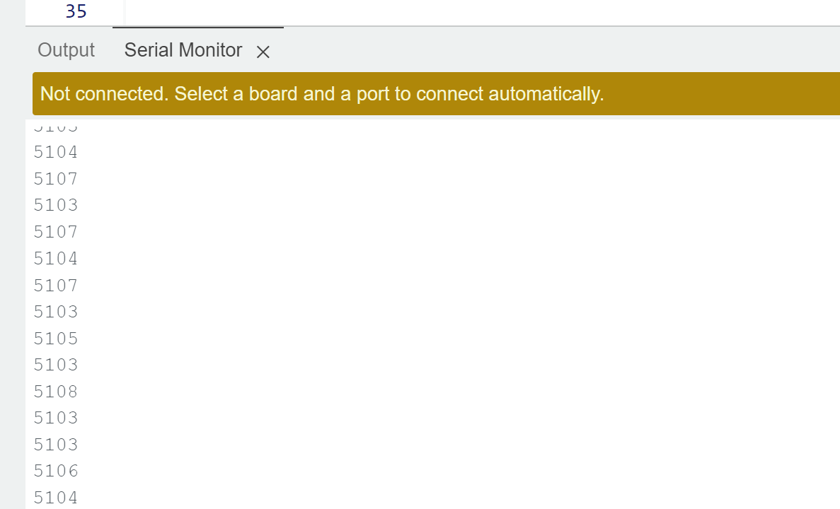
Figure 2: Output of above code
This code gave an output of 5100 microseconds for each signal. This would mean a delay of ~5ms. This is much lower than the delay induced by the IMU and ToF sensors. Thus, I think think this is an acceptable range since we will still be acting or reacting faster than our sensor input.
If I increase the frequency, I’d reduce noise and have more control over the motors. However, if I increase the frequency too much, I may overclock the transistor (probably mosfets) and they could either grow inefficient or break.
Lowest PWM value whlie rolling
I wrote a program that starts slightly above the PWM signal neccessary to overcome friction and then had each signal decrease each second. This by slowly ticking down values, I eventually found my robot moving continuously with 22/255 for my left motor and 32/255 for my right motor.
I wouldn’t reccomend others follow this method exactly as I ended up running up and down a hallway holding my laptop close to my robot so I could get serial outputs of the current PWM signal and then cut power once the robot stopped. I ended up with a slightly sore back.
//right motor
#define motor1a 2
#define motor1b 3
#define m1pwm 45


//left motor
#define motor2a 5
#define motor2b 6
#define m2pwm 55
int cnt=0;

void setup() {
  Serial.begin(115200);
  pinMode(motor1a, OUTPUT);
  pinMode(motor1b, OUTPUT);
  analogWrite(motor1a,0);
  analogWrite(motor1b,0);

  pinMode(motor2a, OUTPUT);
  pinMode(motor2b, OUTPUT);
  analogWrite(motor2a,0);
  analogWrite(motor2b,0);
  delay(15000);
}

void loop() {
  analogWrite(motor1b,55-cnt);
  analogWrite(motor2a,45-cnt);
  Serial.print("motor1b(left): ");
  Serial.print(45-cnt);
  Serial.print("   motor2a(right): ");
  Serial.println(55-cnt);

  delay(2000);
  cnt++;
}