
Fast Robots - Lab 6: Angular PID
Prelab
The goal of this lab was to implement orientation control using a PID controller with the IMU. The robot was tasked with maintaining a fixed orientation, recovering to the set point after being jostled or drifting away. This lab built upon the closed-loop control techniques learned in Lab 5, further refining the PID gains and testing system stability in different conditions.
\[u(t)= k_p * e(t) + k_i * \int_0^t e(t) dt + k_d *\frac{d }{dt}e(t)\]Bluetooth Communication Updates
I first implemented a way to tune my gains over bluetooth.
case SEND_GAINS:{
            float kp_lin, ki_lin, kd_lin;
            float kp_ang, ki_ang, kd_ang;


            // Extract the next value from the command string as an float x3
            success = robot_cmd.get_next_value(kp_lin);
            if (!success)
                return;

            success = robot_cmd.get_next_value(ki_lin);
            if (!success)
                return;

            success = robot_cmd.get_next_value(kd_lin);
            if (!success)
                return;

            success = robot_cmd.get_next_value(kp_ang);
            if (!success)
                return;

            success = robot_cmd.get_next_value(ki_ang);
            if (!success)
                return;

            success = robot_cmd.get_next_value(kd_ang);
            if (!success)
                return;

            kp= kp_lin;
            ki= ki_lin;
            kd= kd_lin;

            kp_a= kp_ang;
            ki_a= ki_ang;
            kd_a= kd_ang;
            Serial.print("Lin Gains: ");
            Serial.print(kp);
            Serial.print(", ");
            Serial.print(ki);
            Serial.print(", ");
            Serial.println(kd);
            Serial.print("Ang Gains: ");
            Serial.print(kp_a);
            Serial.print(", ");
            Serial.print(ki_a);
            Serial.print(", ");
            Serial.println(kd_a);

            break;
        }
Figure 1: Arduino side for Send Gains
kp_lin=0.05
ki_lin=0.01
kd_lin=0.0
kp_ang=0
ki_ang=0
kd_ang=0

ble.send_command(CMD.SEND_GAINS, f'{kp_lin}|{ki_lin}|{kd_lin}|{kp_ang}|{ki_ang}|{kd_ang}')
Figure 2: Python side of Send Gains
Next I created a case statement for angular PID
        case PID_A_BEGIN:{

          // future code
          break;
          }
Figure 3: Angular PID case
My STOP_PID command from last week also carried over as a safety measure.
I also created a turn helper command based on my drive straight command from last week. In some open loop tests, it took a much higher PWM rate to effectively turn the car over driving forward. This makes sense since there is signifigantly more slippage in the system since the front and rear drivetrains are fixed and don’t follow an ackerman geometry.
void turn(int dir, int PWM){
  if (dir == 1){
    //turn clockwise

    analogWrite(motor1a, 0);
    analogWrite(motor1b, int(PWM*cal));
    //analogWrite(motor1b, PWM);
    analogWrite(motor2a, 0);
    analogWrite(motor2b, PWM);
  }
  else if (dir == -1){
    //drive backward

    analogWrite(motor1a, int(PWM*cal));
    analogWrite(motor1b, 0);
    //analogWrite(motor1b, PWM);
    analogWrite(motor2a, PWM);
    analogWrite(motor2b, 0);
  }
  else {
    analogWrite(motor1a, 0);
    analogWrite(motor1b, 0);
    analogWrite(motor2a, 0);
    analogWrite(motor2b, 0);
  }
}
Figure 4: Turn Helper Function
Lab Tasks
Implementing DMP for Orientation Control
I began with a Digital Motion Processing for my IMU since I measured signifigant drift in my IMU during lab 2 testing. This should help rectify that.
For Fast Robots, I use the Pimoroni ICM-20948 9DoF breakout board, which integrates the TDK InvenSense ICM-20948 motion tracking sensor. This sensor includes a digital motion processor (DMP), which performs sensor fusion by combining data from:
- 3-axis gyroscope
- 3-axis accelerometer
- 3-axis magnetometer (compass)
The DMP helps in error correction, drift reduction, and overall enhanced orientation estimation.
Enabling the DMP
By default, the DMP is disabled in the SparkFun ICM-20948 Arduino library due to memory constraints. To enable it:
- Open the
ICM_20948_C.hfile in the SparkFun library folder. - Uncomment line 29 to define
ICM_20948_USE_DMP. - Open
Example7_DMP_Quat6_EulerAnglesin Arduino IDE. - Upload the sketch and use the serial monitor to observe yaw, pitch, and roll values.
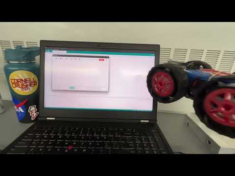
Figure 5: Video of Sensor Values implementing DMP
After confirming DMP was working, I then implemnted this into my begin BEGIN_A_PID case.
        case PID_A_BEGIN:{
            delay(3000);
            int count = 0;
            int distance = 0;
            int pwm=0;
            int dir= 1;
            int err=0;
            int errI=0;
            int errP=0;
            int errD=0;

            float pid_dt=0;
            /////////////////////////////////// dmp loop
            while ((currMillisTOF - prevMillisTOF <= 10000) && (count <= Array_Size)) {
              // Read any DMP data waiting in the FIFO
              // Note:
              //    readDMPdataFromFIFO will return ICM_20948_Stat_FIFONoDataAvail if no data is available.
              //    If data is available, readDMPdataFromFIFO will attempt to read _one_ frame of DMP data.
              //    readDMPdataFromFIFO will return ICM_20948_Stat_FIFOIncompleteData if a frame was present but was incomplete
              //    readDMPdataFromFIFO will return ICM_20948_Stat_Ok if a valid frame was read.
              //    readDMPdataFromFIFO will return ICM_20948_Stat_FIFOMoreDataAvail if a valid frame was read _and_ the FIFO contains more (unread) data.
              icm_20948_DMP_data_t data;
              myICM.readDMPdataFromFIFO(&data);

              if ((myICM.status == ICM_20948_Stat_Ok) || (myICM.status == ICM_20948_Stat_FIFOMoreDataAvail)) // Was valid data available?
              {
                //SERIAL_PORT.print(F("Received data! Header: 0x")); // Print the header in HEX so we can see what data is arriving in the FIFO
                //if ( data.header < 0x1000) SERIAL_PORT.print( "0" ); // Pad the zeros
                //if ( data.header < 0x100) SERIAL_PORT.print( "0" );
                //if ( data.header < 0x10) SERIAL_PORT.print( "0" );
                //SERIAL_PORT.println( data.header, HEX );

                if ((data.header & DMP_header_bitmap_Quat6) > 0) // We have asked for GRV data so we should receive Quat6
                {
                  // Q0 value is computed from this equation: Q0^2 + Q1^2 + Q2^2 + Q3^2 = 1.
                  // In case of drift, the sum will not add to 1, therefore, quaternion data need to be corrected with right bias values.
                  // The quaternion data is scaled by 2^30.

                  //SERIAL_PORT.printf("Quat6 data is: Q1:%ld Q2:%ld Q3:%ld\r\n", data.Quat6.Data.Q1, data.Quat6.Data.Q2, data.Quat6.Data.Q3);

                  // Scale to +/- 1
                  double q1 = ((double)data.Quat6.Data.Q1) / 1073741824.0; // Convert to double. Divide by 2^30
                  double q2 = ((double)data.Quat6.Data.Q2) / 1073741824.0; // Convert to double. Divide by 2^30
                  double q3 = ((double)data.Quat6.Data.Q3) / 1073741824.0; // Convert to double. Divide by 2^30


                  // SERIAL_PORT.print(F("Q1:"));
                  // SERIAL_PORT.print(q1, 3);
                  // SERIAL_PORT.print(F(" Q2:"));
                  // SERIAL_PORT.print(q2, 3);
                  // SERIAL_PORT.print(F(" Q3:"));
                  // SERIAL_PORT.println(q3, 3);


                  // The ICM 20948 chip has axes y-forward, x-right and Z-up - see Figure 12:
                  // Orientation of Axes of Sensitivity and Polarity of Rotation
                  // in DS-000189-ICM-20948-v1.6.pdf  These are the axes for gyro and accel and quat
                  //
                  // For conversion to roll, pitch and yaw for the equations below, the coordinate frame
                  // must be in aircraft reference frame.
                  //
                  // We use the Tait Bryan angles (in terms of flight dynamics):
                  // ref: https://en.wikipedia.org/w/index.php?title=Conversion_between_quaternions_and_Euler_angles
                  //
                  // Heading – ψ : rotation about the Z-axis (+/- 180 deg.)
                  // Pitch – θ : rotation about the new Y-axis (+/- 90 deg.)
                  // Bank – ϕ : rotation about the new X-axis  (+/- 180 deg.)
                  //
                  // where the X-axis points forward (pin 1 on chip), Y-axis to the right and Z-axis downward.
                  // In the conversion example above the rotation occurs in the order heading, pitch, bank.
                  // To get the roll, pitch and yaw equations to work properly we need to exchange the axes

                  // Note when pitch approaches +/- 90 deg. the heading and bank become less meaningfull because the
                  // device is pointing up/down. (Gimbal lock)

                  double q0 = sqrt(1.0 - ((q1 * q1) + (q2 * q2) + (q3 * q3)));

                  double qw = q0; // See issue #145 - thank you @Gord1
                  double qx = q2;
                  double qy = q1;
                  double qz = -q3;

                  // roll (x-axis rotation)
                  double t0 = +2.0 * (qw * qx + qy * qz);
                  double t1 = +1.0 - 2.0 * (qx * qx + qy * qy);
                  double roll = atan2(t0, t1) * 180.0 / PI;

                  // pitch (y-axis rotation)
                  double t2 = +2.0 * (qw * qy - qx * qz);
                  t2 = t2 > 1.0 ? 1.0 : t2;
                  t2 = t2 < -1.0 ? -1.0 : t2;
                  double pitch = asin(t2) * 180.0 / PI;

                  // yaw (z-axis rotation)
                  double t3 = +2.0 * (qw * qz + qx * qy);
                  double t4 = +1.0 - 2.0 * (qy * qy + qz * qz);
                  double yaw = atan2(t3, t4) * 180.0 / PI;
                  time_array[count]=millis();
                  yaw_array[count]= (float)yaw;
                  count++;

            #ifndef QUAT_ANIMATION
                  SERIAL_PORT.print(F("Roll:"));
                  SERIAL_PORT.print(roll, 1);
                  SERIAL_PORT.print(F(" Pitch:"));
                  SERIAL_PORT.print(pitch, 1);
                  SERIAL_PORT.print(F(" Yaw:"));
                  SERIAL_PORT.println(yaw, 1);
            #else
                  // Output the Quaternion data in the format expected by ZaneL's Node.js Quaternion animation tool
                  // SERIAL_PORT.print(F("{\"quat_w\":"));
                  // SERIAL_PORT.print(q0, 3);
                  // SERIAL_PORT.print(F(", \"quat_x\":"));
                  // SERIAL_PORT.print(q1, 3);
                  // SERIAL_PORT.print(F(", \"quat_y\":"));
                  // SERIAL_PORT.print(q2, 3);
                  // SERIAL_PORT.print(F(", \"quat_z\":"));
                  // SERIAL_PORT.print(q3, 3);
                  // SERIAL_PORT.println(F("}"));
            #endif
                }
              }

              if (myICM.status != ICM_20948_Stat_FIFOMoreDataAvail) // If more data is available then we should read it right away - and not delay
              {
                delay(10);
              }
            }
           for (int i = 0; i < count; i++) {
              tx_estring_value.clear();
              tx_estring_value.append(time_array[i]);
              tx_estring_value.append(" | ");
              tx_estring_value.append(yaw_array[i]);
              // tx_estring_value.append(" | ");
              // tx_estring_value.append(PWM_array[i]);
              tx_characteristic_string.writeValue(tx_estring_value.c_str());
            }

          break;
          }
Figure 6: DMP implemntation over bluetooth
I then collected while rotating my robot ~90 degrees every second or two.
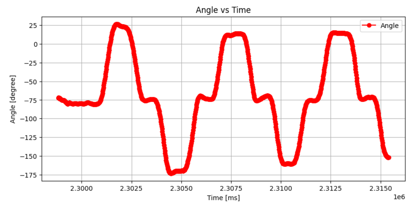
Figure 7: Yaw vs Time graph
Even with the extra DMP math, the data collection rate is still signifigantly faster than the ToF sensor collection rate. This is even before optimzing the code at all. After optimizing, I’ll start implementing PID control.
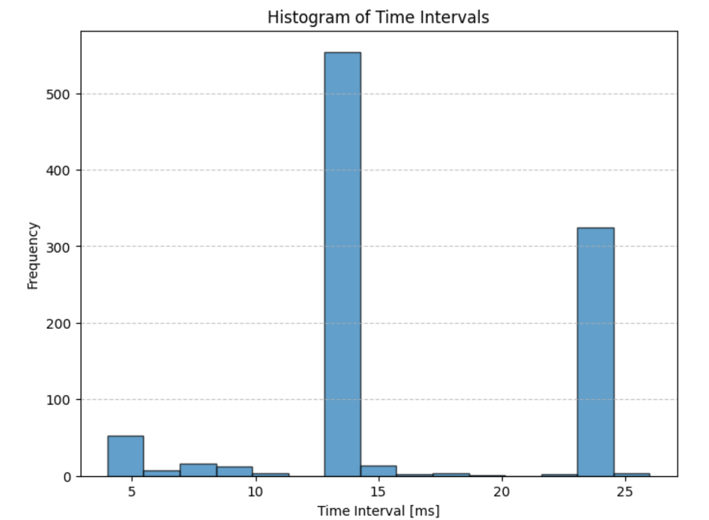
Figure 8: Timing Histogram
P Control
        case PID_A_BEGIN:{
            delay(2000);
            int count = 0;
            int distance = 0;
            int target=0;
            int pwm=0;
            int dir= 0;
            int err=0;
            int errI=0;
            int errP=0;
            int errD=0;
            float pid_dt=0;
            //clear arrays
            memset(time_array, 0, sizeof(time_array));
            memset(yaw_array, 0, sizeof(yaw_array));
            memset(PWM_array, 0, sizeof(PWM_array));
            memset(err_array, 0, sizeof(err_array));

            ///////////////////////////////////  loop
            while ((currMillisTOF - prevMillisTOF <= 10000) && (count <= Array_Size)) {
                 icm_20948_DMP_data_t data;
              myICM.readDMPdataFromFIFO(&data);

              if ((myICM.status == ICM_20948_Stat_Ok) || (myICM.status == ICM_20948_Stat_FIFOMoreDataAvail)) // Was valid data available?
              {
                if ((data.header & DMP_header_bitmap_Quat6) > 0) // We have asked for GRV data so we should receive Quat6
                {

                  double q1 = ((double)data.Quat6.Data.Q1) / 1073741824.0; // Convert to double. Divide by 2^30
                  double q2 = ((double)data.Quat6.Data.Q2) / 1073741824.0; // Convert to double. Divide by 2^30
                  double q3 = ((double)data.Quat6.Data.Q3) / 1073741824.0; // Convert to double. Divide by 2^30

                  double q0 = sqrt(1.0 - ((q1 * q1) + (q2 * q2) + (q3 * q3)));

                  double qw = q0; // See issue #145 - thank you @Gord1
                  double qx = q2;
                  double qy = q1;
                  double qz = -q3;

                  // yaw (z-axis rotation)
                  double t3 = +2.0 * (qw * qz + qx * qy);
                  double t4 = +1.0 - 2.0 * (qy * qy + qz * qz);
                  double yaw = atan2(t3, t4) * 180.0 / PI;
                      ////////////////////////////////////////////////////////////////////////////////PID CONTROL+
                                    //Serial.println("enter pid loop");

                                    time_array[count]=millis();
                                    yaw_array[count]= (float)yaw;


                                      pid_dt= time_array[count]-time_array[count-1];
                                      errP = (float)(yaw - target );
                                      errI=0;

                                      err= (float) errP+errI;
                                      pwm= (int) (kp_a*errP)+(ki_a*errI);
                                    Serial.print("error: ");
                                    Serial.println(err);


                                      //Serial.print("    dir: ");

                                      if (err > 0){
                                        //turn clock wise
                                        dir=1;
                                        //Serial.print(" clockwise    ");

                                      }

                                      else if (err < 0){
                                        // turn c clockwise
                                        dir= (-1);
                                        //Serial.print(" counter clockwise    ");
                                      }
                                      pwm= abs(pwm);

                                      if (pwm < pwmMinA ) pwm = pwmMinA;
                                      if (pwm > pwmMax ) pwm = pwmMax;

                                      Serial.println(dir);

                                      turn(dir, pwm);
                                      PWM_array[count] = (dir*pwm);
                                      err_array[count]= err;
                      ////////////////////////////////////////////////////////////////////////////////PID CONTROL-
                  count++;
                }
              }

              if (myICM.status != ICM_20948_Stat_FIFOMoreDataAvail) // If more data is available then we should read it right away - and not delay
              {
                delay(10);
              }
            }

             turn(0, 0);


           for (int i = 0; i < count; i++) {
              tx_estring_value.clear();
              tx_estring_value.append(time_array[i]);
              tx_estring_value.append(" | ");
              tx_estring_value.append(yaw_array[i]);
              tx_estring_value.append(" | ");
              tx_estring_value.append(PWM_array[i]);
              tx_estring_value.append(" | ");
              tx_estring_value.append(err_array[i]);
              tx_characteristic_string.writeValue(tx_estring_value.c_str());
            }
          break;
          }
Figure 9: P Control Code

Figure 10: P Control in action (i kick the crap out of this car)
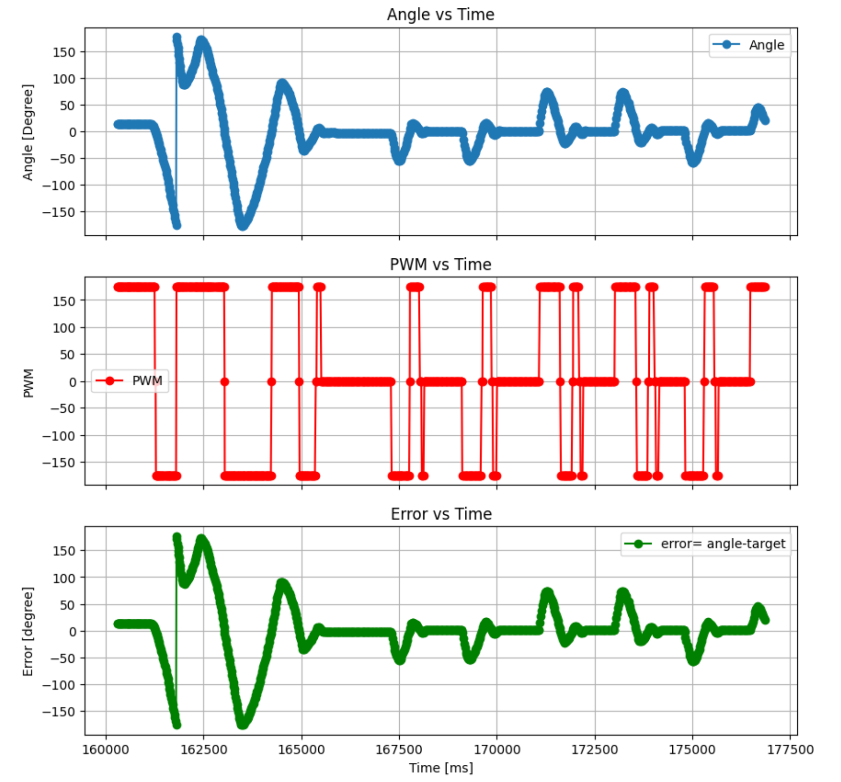
Figure 11: Angle, PWM, Error vs Time
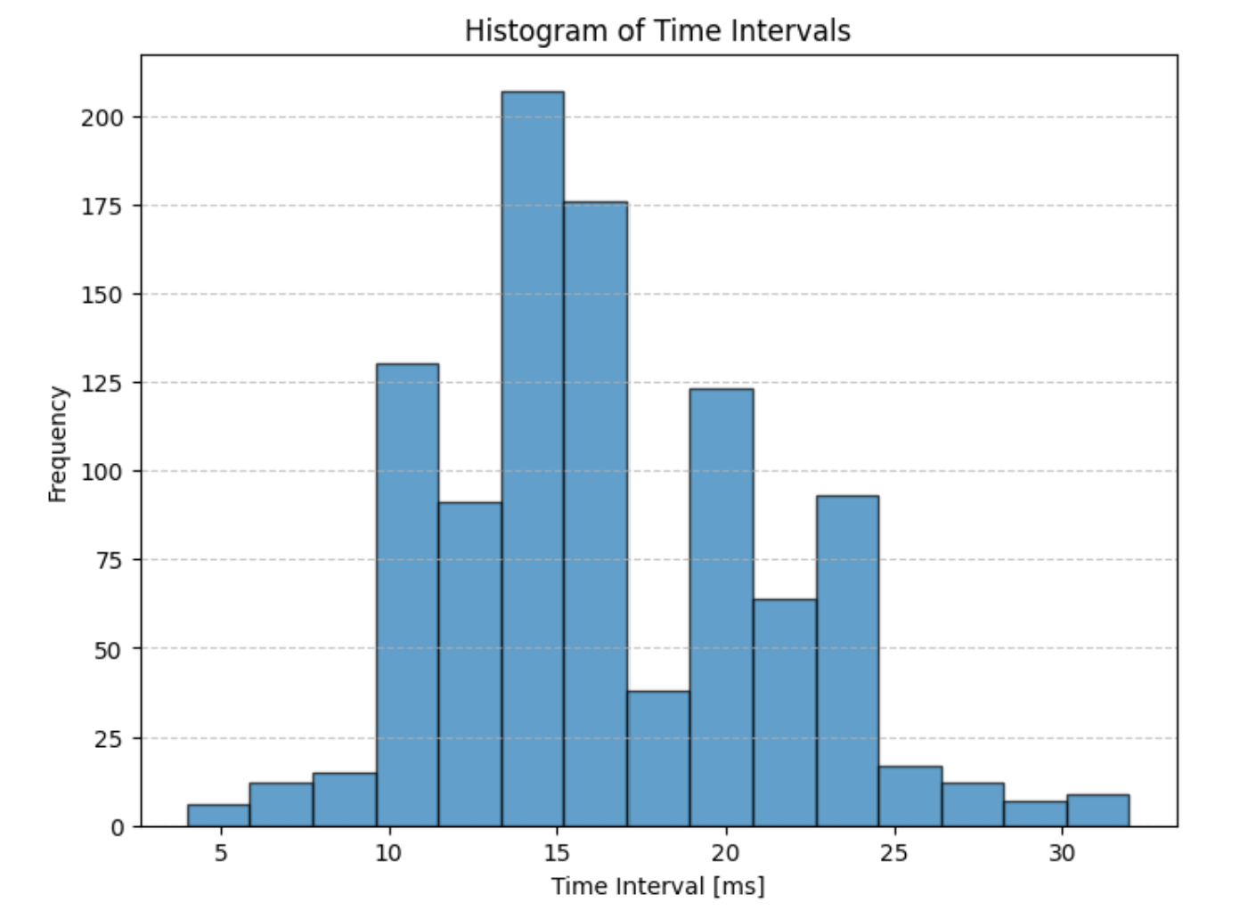
Figure 12: Timing Histogram
Overall, I think the P Controller performance is pretty good. My kp=1.5 and the timing values are distrubted around 15 ms with 90% of the values between 5-25 ms. I’m pretty happy with this since it’s signifigantly faster than my ToF rate, so I don’t think it’ll be a bottleneck for future projects.
The behavior at the very begining is odd with wild fluctuations. However, eventually the robot settles and is then very quick to recover when kicked. I suspect that the initial high error prompts a large response and the inertia of the robot carrys it through the opposite regime after passing the target of 0 degrees. More testing to come.
PI Control
  pid_dt= time_array[count]-time_array[count-1];
  errP = (float)(yaw - target );
  errI= (float) errI+ err*pid_dt/1000;
  //errI=0;
  if (errI > 150){
    errI=150;
  }
  else if (errI < -150){
    errI=-150;
  }
  err= (float) errP+errI;
  pwm= (int) (kp_a*errP)+(ki_a*errI);
Figure 13: PI Control Implementation

Figure 14: PI Control in action
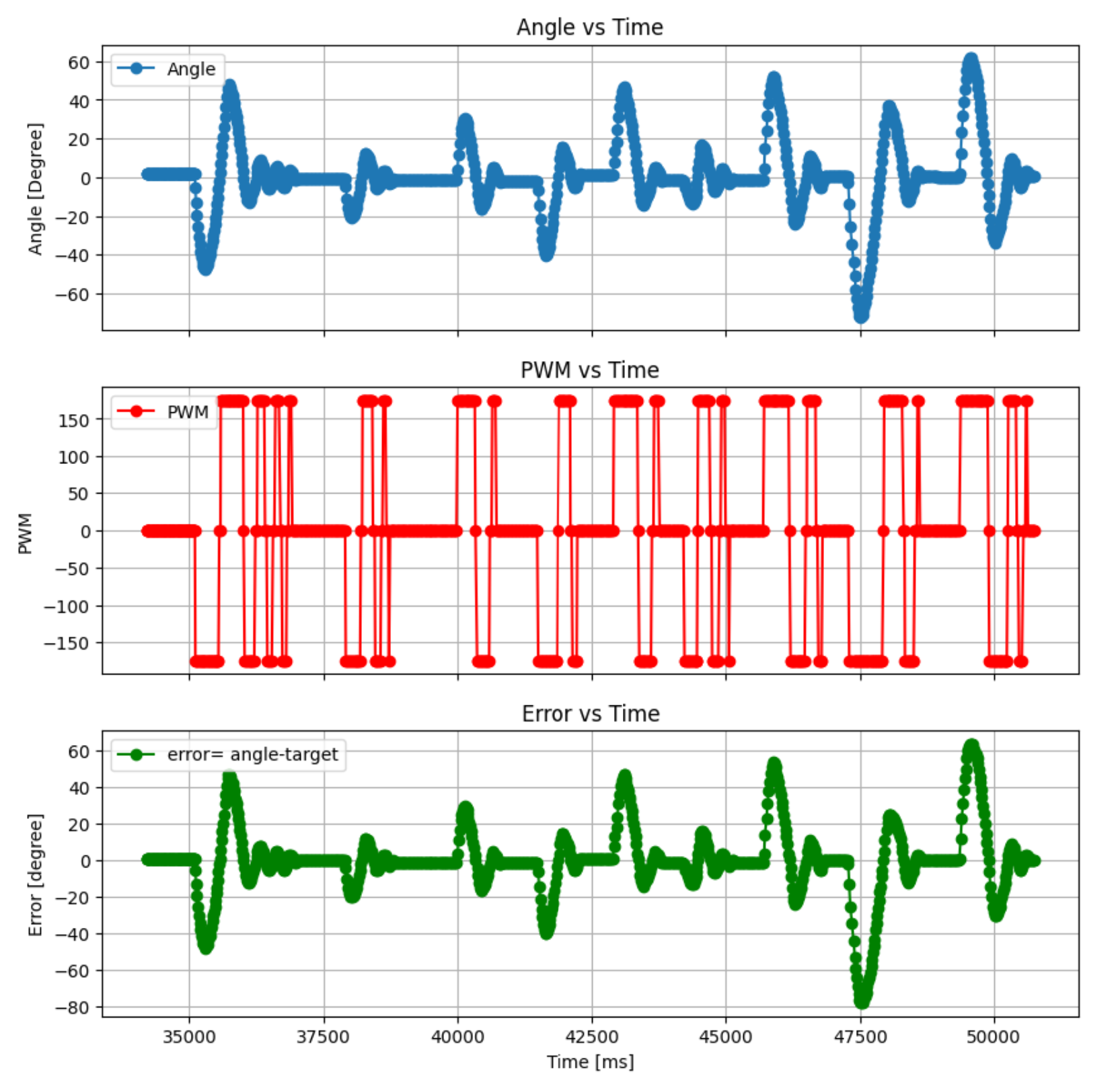
Figure 15: Angle, PWM, Error vs Time
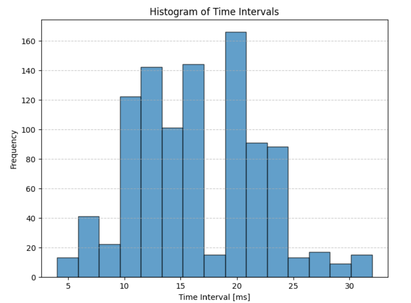
Figure 16: Timing Histogram
I’m very satisfied with the performance of the PI controller. It seems to settle ~30% faster than my P controller and has somehow resolved the weird bug where the car would spin around once at startup. I’m not actually sure why that’s not happening anymore, but it shouldn’t have been happening in the first place so I’m happy about it regardless. My gains here were kp=1.5 and ki=0.3. I wanted to keep my ki term relatively small and this one worked quite well during testing.
My PI control seems to take slightly longer than P on average. The median value is slihtly higher for PI than P, but only by 1-2 ms. The variance is also higher for this case. Despite these changes, teh performance is still quite good and I feel PI is an improvement over P control.
Integrator Windup
if (errI > 150){
    errI=150;
  }
  else if (errI < -150){
    errI=-150;
  }
Figure 17: Integrator windup code
I implementated integrator windup safeguards from the start this time since I had pretty rough results without it last lab. I set my bounds at +/- 150 so with a ki=0.30, the maximum integrator component would be 45.
Discussion
Overall I’m quite happy with the results of this controller. There are still some slight oscillations which ideally wouldn’t be there, but I think some of this may be unavoidable due to the limited PWM band (175-255) and slippage in the wheels. With further tuning I may be able to tune this down further. Overall, this lab went much smoother than Linear PID, but that’s a pretty low bar lol. Already having some PID experience with last week was certainly helpful. This was a lot of work, but felt fun!